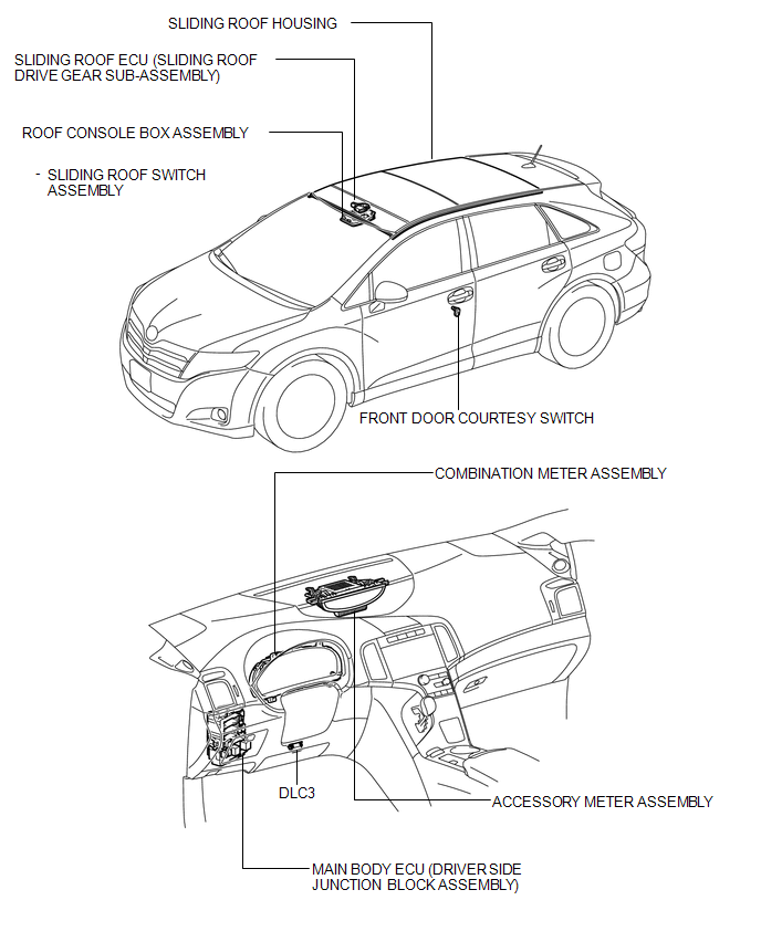
Toyota Venza: Parts Location
PARTS LOCATION
ILLUSTRATION
 Precaution
PRECAUTION
NOTICE:
When disconnecting the cable from the negative (-) battery terminal, initialize
the following systems after the cable is reconnected.
System Name
See Proc ...
 System Diagram
SYSTEM DIAGRAM
Communication Table
Sender
Receiver
Signal
Line
Main body ECU (Driver side junction block assembly)
Sliding ro ...
Other materials about Toyota Venza:
Lubrication System
On-vehicle Inspection
ON-VEHICLE INSPECTION
PROCEDURE
1. INSPECT ENGINE OIL LEVEL
(a) Warm up the engine, stop it and wait 5 minutes. The engine oil level should
be between the low level mark and full level mark on the engine oil level dipstick.
If th ...
Installation
INSTALLATION
PROCEDURE
1. INSTALL VACUUM SWITCHING VALVE ASSEMBLY (for ACIS)
(a) Install the vacuum switching valve assembly (for ACIS) with the bolt.
Torque:
9.0 N·m {92 kgf·cm, 80 in·lbf}
...
Installation
INSTALLATION
PROCEDURE
1. INSTALL POWER SEAT SWITCH
(a) Install the power seat switch with the 3 screws.
(b) Connect the connector.
2. INSTALL FRONT SEAT CUSHION SHIELD ASSEMBLY
3. INSTALL SLID ...

0.1211