Toyota Venza: System Diagram
SYSTEM DIAGRAM
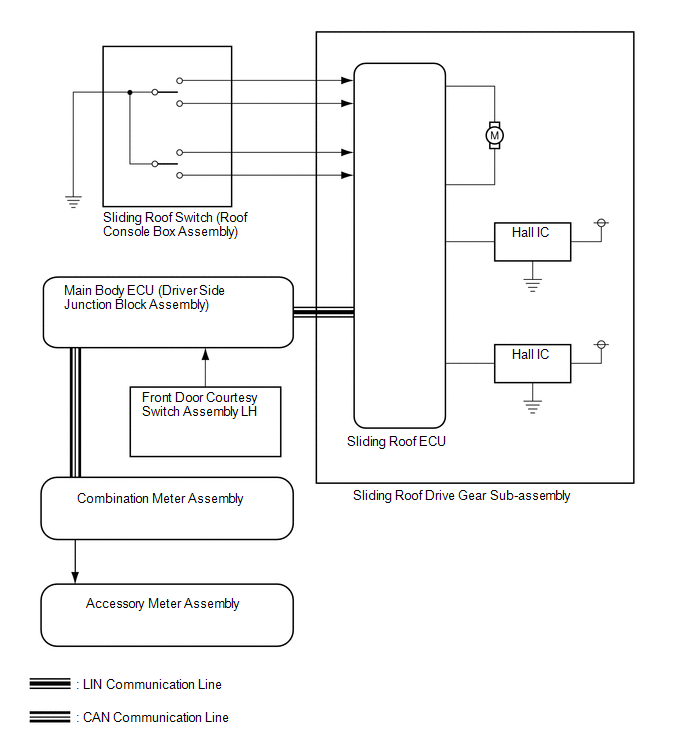 Communication Table
|
Sender |
Receiver |
Signal |
Line |
|---|---|---|---|
|
Main body ECU (Driver side junction block assembly) |
Sliding roof ECU (Sliding roof drive gear sub-assembly) |
Key off operation signal |
LIN |
|
Main body ECU (Driver side junction block assembly) |
Combination meter assembly |
Sliding roof open warning signal |
CAN |
 Parts Location
PARTS LOCATION
ILLUSTRATION
...
 System Description
SYSTEM DESCRIPTION
1. GENERAL
This system has the following functions: manual slide open and close; auto slide
open; manual tilt up and down; auto tilt up; jam protection; key off operation.
2. F ...
Other materials about Toyota Venza:
Disassembly
DISASSEMBLY
PROCEDURE
1. REMOVE NO. 1 AIR DUCT SUB-ASSEMBLY
(a) Disengage the 4 claws and remove the No. 1 air duct sub-assembly.
2. REMOVE AIR FILTER COVER PLATE
(a) Disengage the 2 cla ...
Dtc Check / Clear
DTC CHECK / CLEAR
1. CHECK DTC
(a) Connect the Techstream to the DLC3.
(b) Turn the ignition switch to ON.
(c) Turn the Techstream on.
(d) Enter the following menus: Body Electrical / (desired system) / Trouble Codes.
(e) Check the details of the DTC(s) ...
Lost Communication with Rear Airbag Sensor RH (B1632/81,B1633/81,B1642/81,B1692/81,B1693/81)
DESCRIPTION
The side collision sensor RH circuit (to determine deployment of the front seat
side airbag assembly RH and curtain shield airbag assembly RH) is composed of the
center airbag sensor assembly, rear airbag sensor RH and side airbag sensor RH.
...

0.15