Toyota Venza: Parts Location
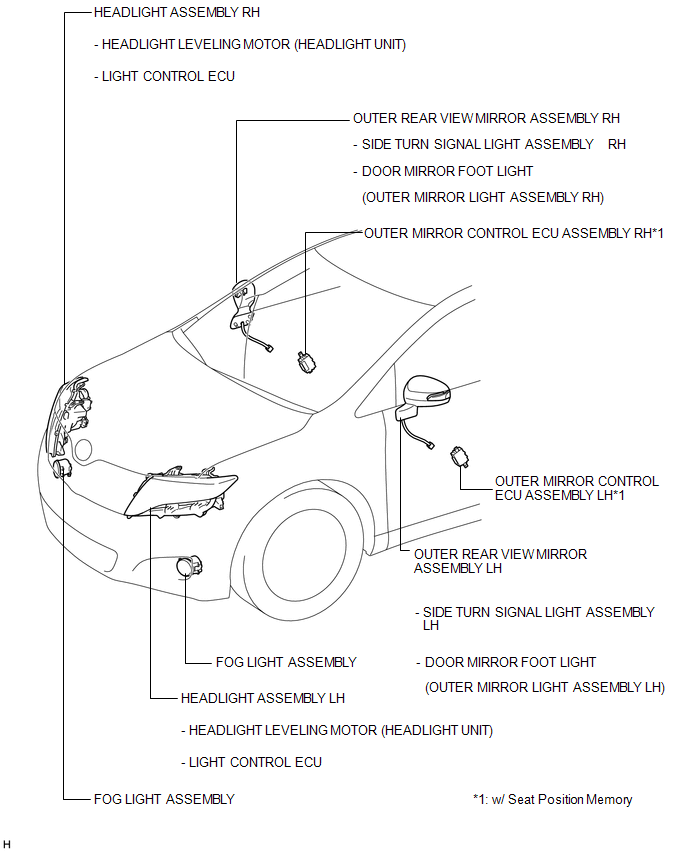
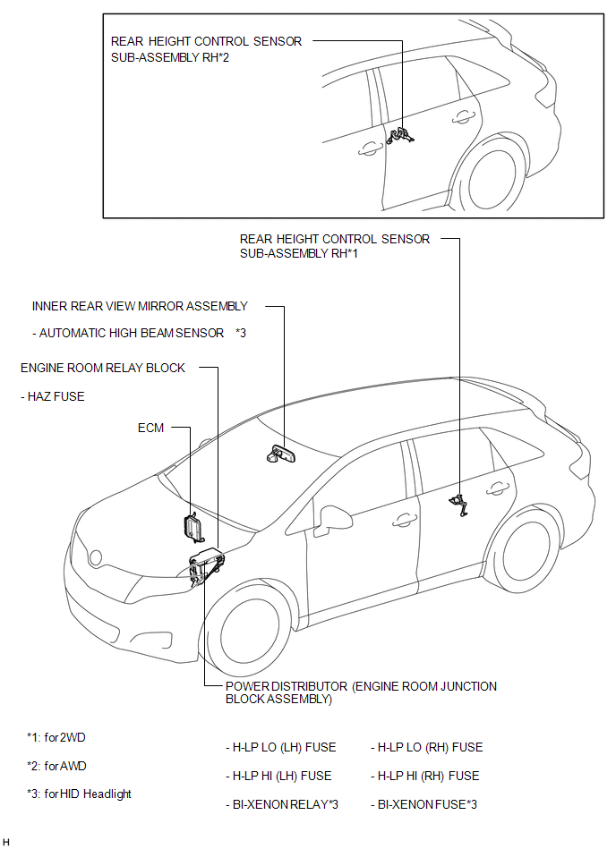
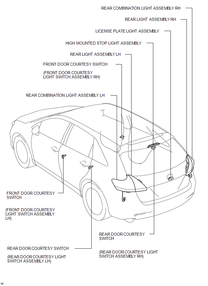
PARTS LOCATION
ILLUSTRATION
ILLUSTRATION
ILLUSTRATION
ILLUSTRATION
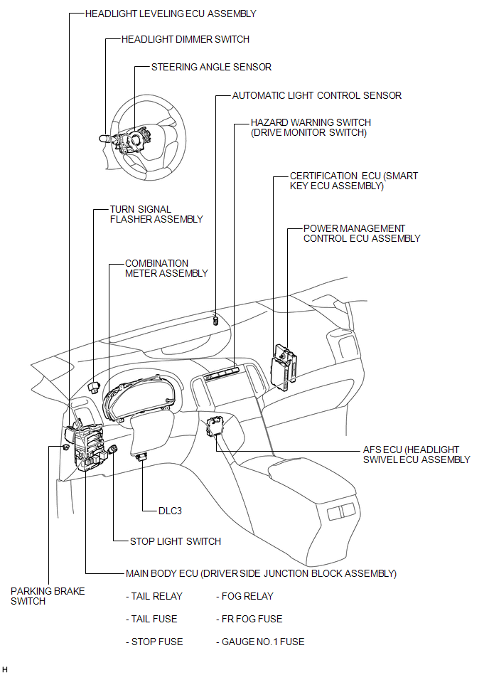
 Lighting System
...
 Precaution
PRECAUTION
NOTICE:
When disconnecting the cable from the negative (-) battery terminal, initialize
the following systems after the cable is reconnected.
System Name
See Proc ...
Other materials about Toyota Venza:
Terminals Of Ecu
TERMINALS OF ECU
1. CHECK AIR CONDITIONING AMPLIFIER ASSEMBLY
(a) Disconnect the D47 air conditioning amplifier assembly connector.
(b) Measure the voltage and resistance according to the value(s) in the table
below.
HINT:
Measure the values on the wi ...
Rocker Panel Moulding
Components
COMPONENTS
ILLUSTRATION
Removal
REMOVAL
PROCEDURE
1. REMOVE FRONT FENDER OUTSIDE MOULDING
2. REMOVE NO. 2 ROCKER PANEL MOULDING PROTECTOR
3. REMOVE REAR ROCKER PANEL MOULDING END COVER
4. REMOVE BODY ROCKER PANEL MOULDING ASS ...
Inspection
INSPECTION
PROCEDURE
1. INSPECT SHIFT SOLENOID VALVE SL
(a) Measure the resistance according to the value(s) in the table below.
Text in Illustration
*1
Shift Solenoid Valve SL
Standard Re ...

0.1636