Toyota Venza: Parts Location
PARTS LOCATION
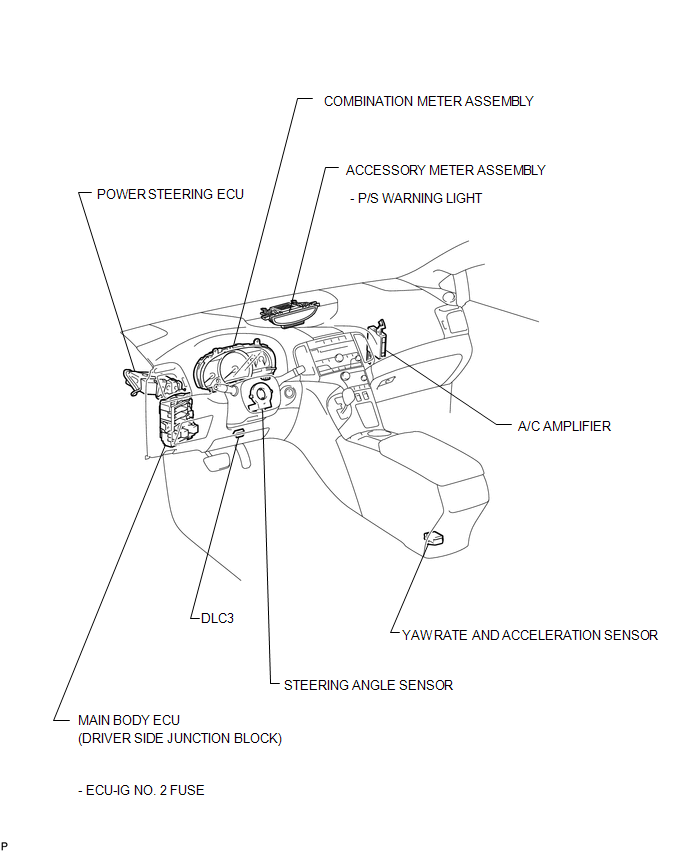
ILLUSTRATION
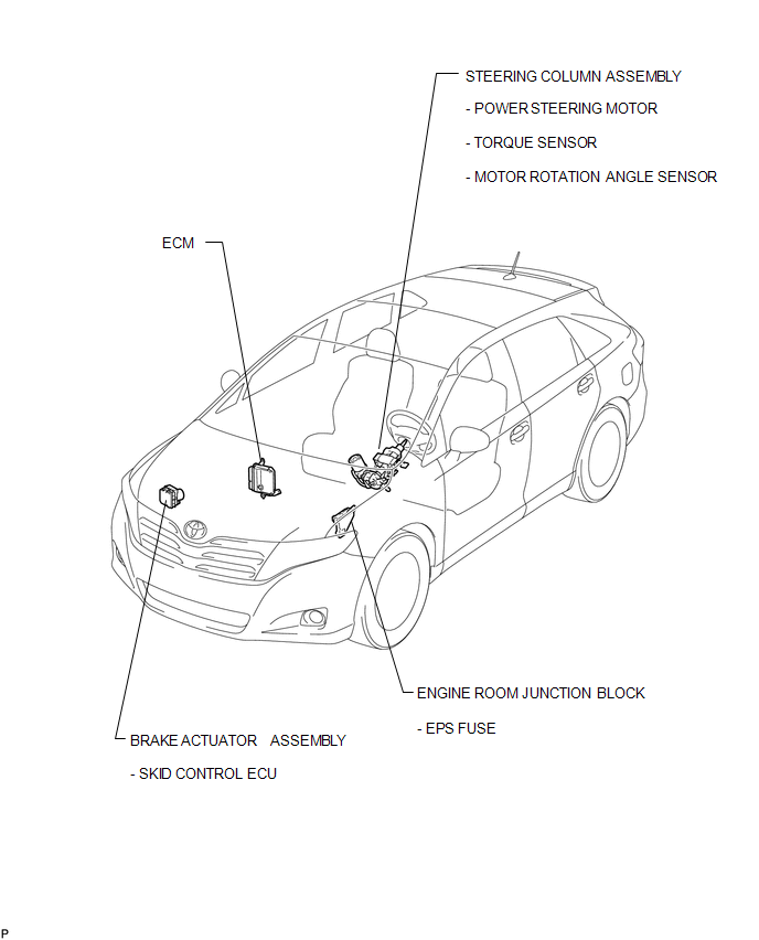
ILLUSTRATION

 Precaution
PRECAUTION
1. PRECAUTION FOR DISCONNECTING THE BATTERY CABLE
NOTICE:
When disconnecting the cable from the negative (-) battery terminal, initialize
the following systems after the cable is recon ...
Other materials about Toyota Venza:
System Diagram
SYSTEM DIAGRAM
1. CAN AND DIRECT LINE SIGNALS
2. INPUT AND OUTPUT SIGNALS OF THE ACCESSORY METER ASSEMBLY
Warning light or indicator light
Communication Signal
Receiver
Communication Line
Sender
...
Registration
REGISTRATION
PROCEDURE
1. DESCRIPTION OF CODE REGISTRATION
HINT:
The ID codes are the same as recognition codes for the wireless transmitter
and the engine immobiliser function. Registering an ID code enables the
smart key system, the wirel ...
Satellite Radio Broadcast cannot be Received
CAUTION / NOTICE / HINT
NOTICE:
Some satellite radio broadcasts require payment. A contract must be made between
a satellite radio company and the user. If the contract expires, it will not be
possible to listen to the broadcast.
PROCEDURE
1 ...

0.1124