Toyota Venza: Operation Check
OPERATION CHECK
1. SMART KEY SYSTEM OPERATION INSPECTION
(a) Check the entry unlock function.
(1) Use the wireless lock operation to lock the doors. With the key outside the vehicle, touch a front door outside handle assembly (touch sensor) and check that the door unlocks.
(b) Check the entry unlock operation detection area.
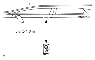
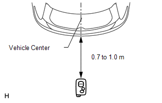
(1) Step 1: Hold the key at the same height as the door outside handle assembly (approximately 0.8 m (2.62 ft.)). Make sure that the direction of the key is as shown in the illustration.
(2) Step 2: Check that when the key is brought within 0.7 to 1.0 m (2.30 to 3.28 ft.) of the vehicle, the system enters unlock standby mode.
HINT:
When the system enters unlock standby mode, the key LED illuminates.
(3) Step 3: After the system enters unlock standby mode, touch the door outside handle assembly (touch sensor) within 3 seconds. Check that the door unlocks.
NOTICE:
The key may not be able to communicate with the system within a 0.2 m (0.656 ft.) radius of each door outside handle assembly.
(4) Step 4: Repeat step 2 and 3 for the remaining front door.
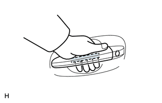
(5) Step 5: Inspect the door outside handle assembly (touch sensor) response sensitivity. When the system is in unlock standby mode, check that touching the area shown in the illustration causes the door to unlock.
NOTICE:
When touching the highlighted area, touching too quickly or having extended contact may not trigger the sensor. In such a case, the door will not unlock.
(6) Step 6: Repeat step 5 for the remaining front door.
(c) Check the entry lock function.
NOTICE:
If the key is in the cabin, but is not in a detection area (on the instrument panel, rear tray, in the glove box, or on the floor), the key confinement function may not operate. This can result in the key confinement.
(1) Step 1: Confirm that all the doors lock when a lock sensor on a front door outside handle is touched with all the doors closed and unlocked while the key is outside of the vehicle.
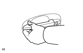
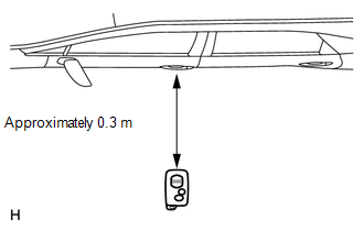
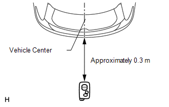
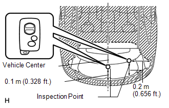
(2) Step 2: Inspect the smart door lock detection area. Hold the key 0.1 m (0.328 ft.) below the window (about 1m (3.28 ft.) above the ground). Move the key about 0.3 m (0.984 ft.) away from the vehicle and touch the lock sensor as shown in the illustration to check that the all doors lock.
HINT:
- Due to the key being unable to communicate with the system from within 0.2 m ( 0.656 ft.) of the door handle, the lock sensor may not operate when the lock sensor is touched by the same hand that is holding the key.
- If the key confinement prevention function buzzer sounds, radio waves from the indoor electrical oscillator may be leaking from the vehicle.
(d) Check the entry back door open function.
(1) Close the back door. With the key outside the vehicle, check that pushing the back door opener switch assembly opens the back door.
(2) Inspect the entry back door open operation detection area. Hold the key at the same height as the back door opener switch assembly (approximately 0.8 m (2.62 ft.)) aligning it with the center of the rear of the vehicle. Make sure that the direction of the key is as shown in the illustration. Check that when the key is brought within 0.7 to 1.0 m (2.30 to 3.28 ft.) of the vehicle, pushing the back door opener switch assembly opens the back door.
(e) Check the entry back door lock function.
(1) Close all of the vehicle doors. With the key in your possession outside of the vehicle, check that pushing the back door opener switch assembly (lock switch) locks all the doors.
HINT:
- When pressing the lock switch, hold the key about 1 m (3.28 ft.) above the ground and about 0.3 m (0.984 ft.) away from the vehicle as shown in the illustration.
- Due to the key being unable to communicate with the system from within 0.2 m ( 0.656 ft.) of the door handle, the lock sensor may not operate when the lock sensor is touched by the same hand that is holding the key.
- If the key confinement prevention function buzzer sounds, radio waves from the indoor electrical oscillator may be leaking from the vehicle.
(f) Check the entry ignition function.
(1) While holding the key, confirm that the engine switch indicator light illuminates green when the engine switch is off, the shift lever is in P and the brake pedal is depressed. With the engine switch indicator illuminates green, confirm that the engine starts when the engine switch is pressed.
(2) While holding the key, confirm that the engine switch turns off → on (ACC) → on (IG) → off every time the engine switch is pressed when the brake pedal is not depressed.
HINT:
When the engine switch is pressed with the engine switch on (IG) and the shift lever is in any position except P, the engine switch will not turn off but remain on (ACC).
(3) With the engine running, vehicle stopped and shift lever in P, confirm that pressing the engine switch turns the engine off, and that the steering lock engages after opening the driver door.
HINT:
When the engine switch is pressed with the engine switch on (IG) and the shift lever in any position except P, the engine switch will not turn off but remain on (ACC).
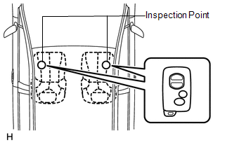
(4) Inspect the detection area for the entry ignition function (for front floor). Make sure that the direction of the key is as shown in the illustration. When the key is in either of the 2 inspection points shown in the illustration, check that the engine can start.
NOTICE:
The engine may not start when the key is on the instrument panel, rear package tray or in the glove box.
(5) Inspect the detection area for the entry ignition function (for center floor). Make sure that the direction of the key is as shown in the illustration. When the key is in either of the 2 inspection points shown in the illustration, check that the engine can start.
NOTICE:
The engine may not start when the key is on the instrument panel, rear package tray or in the glove box.
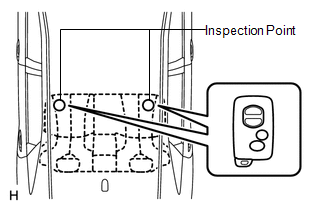
(6) Inspect the detection area for the entry ignition function (for rear floor). Make sure that the direction of the key is as shown in the illustration. When the key is in either of the 2 inspection points shown in the illustration, check that the engine can start.
NOTICE:
The engine may not start when the key is on the instrument panel, rear package tray or in the glove box.
(g) Check the key confinement prevention function (in cabin)
NOTICE:
Perform this check with a window open to prevent key confinement.
(1) Turn the engine switch off.
(2) Put the key on a front seat or a rear seat.
(3) Close all the doors (all doors are in unlocked state).
(4) Confirm that the door lock does not operate but the wireless door lock buzzer sounds for 10 seconds when a front door lock sensor is touched.
(h) Check the key cancel function.
(1) While the engine switch is on (IG), check that the back door opener switch assembly (opener switch) is the only switch that can be operated in the smart key system.
(2) While the key cancel function (smart key system cancel function) is on, check that all functions of the smart key system cannot be operated.
(i) Check the answer-back function (hazard warning light flashing and buzzer sounding).
|
Entry Operation |
Hazard Warning Light |
Buzzer |
|---|---|---|
|
Entry Door Lock |
Flashes once |
Sounds once |
|
Entry Door Unlock |
Flashes twice |
Sounds twice |
|
Entry Back Door Open |
Does not flash |
Does not sound |
(j) Check that the key reminder warning buzzer sounds.
(1) With the key inside the vehicle, close the driver door. Then turn the engine switch off or on (ACC).
(2) Open the driver door and check that the buzzer sounds intermittently.
(k) Check that the key reminder warning buzzer stops.
(1) When the buzzer is sounding, check that the buzzer stops sounding if either of the following is performed:
- Close the driver door (front door courtesy light switch is off).
- Turn the engine switch on (IG).
2. KEY DIAGNOSTIC MODE
HINT:
Key diagnostic mode checks if the key within a selected oscillator detection area is operating normally. The results are output through the wireless door lock buzzer.
(a) Connect the Techstream to the DLC3.
(b) Turn the engine switch on (IG).
(c) Turn the Techstream on.
(d) Enter the following menus: Body Electrical / Smart Key / Key Communication Check.
(e) Check the values by referring to the table below.
Entry & Start (Certification ECU (Smart Key ECU Assembly))|
Tester Display |
Inspection Range |
|---|---|
|
Overhead + Driver Side*1 |
Door electrical key oscillator (for driver side) |
|
Overhead + Passenger Side*2 |
Door electrical key oscillator (for front passenger side) |
|
Overhead + Front Room*3 |
Indoor electrical key oscillator (for front floor) |
|
Overhead + Rear Room*4 |
Indoor electrical key oscillator (for center floor) |
|
Overhead + Back Door (inside)*5 |
Indoor electrical key oscillator (for rear floor) |
|
Overhead + Back Door*6 |
Outside electrical key oscillator (for rear side) |
(f) When the key is brought near the selected oscillator, check that the wireless door lock buzzer sounds.
(1) *1: Door electrical key oscillator (for driver side)
HINT:
- Hold the key at the same height as the door outside handle assembly (0.7 to 1.0 m (2.30 to 3.28 ft.)). Make sure that the direction of the key is as shown in the illustration.
- *2: Perform the same inspection above for the door electrical key oscillator (for front passenger side).
(2) *3: Indoor electrical key oscillator (for front floor)
HINT:
Place the key on the driver or front passenger seat cushion.
(3) *4: Indoor electrical key oscillator (for center floor)
HINT:
Place the key on the rear No. 1 seat cushion.
(4) *5: Indoor electrical key oscillator (for rear floor)
HINT:
Place the key on the luggage area.
(5) *6: Outside electrical key oscillator (for rear side)

HINT:
Hold the key at the same height as the rear bumper upper surface and align with the center of the rear of the vehicle, as shown in the illustration.
 How To Proceed With Troubleshooting
CAUTION / NOTICE / HINT
HINT:
Use the following procedure to troubleshoot the smart key system.
*: Use the Techstream.
PROCEDURE
1.
VEHICLE BROUGHT TO W ...
 Customize Parameters
CUSTOMIZE PARAMETERS
1. CUSTOMIZING FUNCTION WITH TECHSTREAM
HINT:
The items in the table below can be customized.
NOTICE:
When the customer requests a change in a function, first make su ...
Other materials about Toyota Venza:
Installation
INSTALLATION
CAUTION / NOTICE / HINT
NOTICE:
When disconnecting the steering intermediate shaft assembly and pinion shaft
of steering gear assembly, be sure to place matchmarks before servicing.
PROCEDURE
1. INSTALL TIE ROD ASSEMBLY LH
(a) I ...
Diagnosis System
DIAGNOSIS SYSTEM
1. DESCRIPTION
(a) The power window control system data can be read from the Data Link Connector
3 (DLC3) of the vehicle. When the system seems to be malfunctioning, use the Techstream
to check for malfunctions and perform repairs.
2. C ...
Camshaft Position "A" - Timing Over-Advanced or System Performance (Bank 1)
(P0011,P0012)
DESCRIPTION
Refer to DTC P0010 (See page ).
DTC No.
DTC Detection Condition
Trouble Area
P0011
The valve timing is stuck at a certain value when in the advance range
(1 trip detection logic).
...

0.172