Toyota Venza: Open in Inside Luggage Compartment Electrical Key Oscillator Circuit (B27A7)
DESCRIPTION
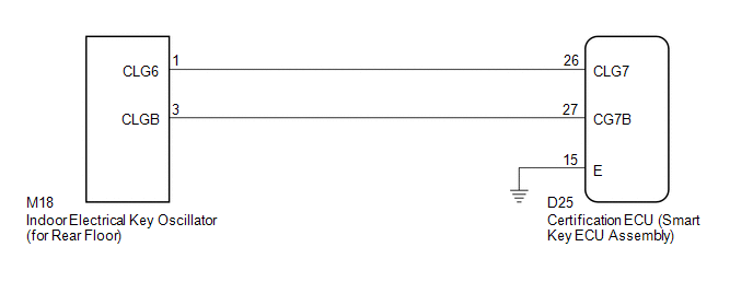
The certification ECU (smart key ECU assembly) generates a request signal and sends it to the indoor electrical key oscillator (for rear floor). To detect the key inside the cabin, the indoor electrical key oscillator (for rear floor) creates a detection area in the cabin.
DTC B27A7 is detected by the certification ECU (smart key ECU assembly) when an open circuit occurs between the certification ECU (smart key ECU assembly) and indoor electrical key oscillator (for rear floor) terminals (between CLG7 and CLG6, or CG7B and CLGB).
|
DTC No. |
DTC Detection Condition |
Trouble Area |
|---|---|---|
|
B27A7 |
Open circuit detected between the certification ECU (smart key ECU assembly) and indoor electrical key oscillator (for rear floor) terminals (between CLG7 and CLG6, or CG7B and CLGB). |
|
WIRING DIAGRAM
CAUTION / NOTICE / HINT
NOTICE:
The smart key system (for entry function) uses a multiplex communication system
(LIN communication system) and CAN communication system. Inspect the communication
function by following How to Proceed with Troubleshooting (See page
.gif) ). Troubleshoot the smart key system (for entry
). Troubleshoot the smart key system (for entry
function) after confirming that the communication system is functioning properly.
PROCEDURE
|
1. |
CHECK CONNECTOR CONNECTION CONDITION |
(a) Turn the engine switch off.
(b) Check that the connectors are properly connected to the certification ECU (smart key ECU assembly) and the indoor electrical key oscillator (for rear floor).
OK:
Connectors are properly connected.
| NG | .gif) |
CONNECT CONNECTORS PROPERLY |
|
.gif)
|
2. |
CHECK HARNESS AND CONNECTOR (CERTIFICATION ECU - INDOOR ELECTRICAL KEY OSCILLATOR) |
(a) Disconnect the certification ECU (smart key ECU assembly) connector.
|
(b) Disconnect the indoor electrical key oscillator (for rear floor) connector. |
|
(c) Measure the resistance according to the value(s) in the table below.
Standard Resistance:
|
Tester Connection |
Condition |
Specified Condition |
|---|---|---|
|
D25-26 (CLG7) - M18-1 (CLG6) |
Always |
Below 1 Ω |
|
D25-27 (CG7B) - M18-3 (CLGB) |
Always |
Below 1 Ω |
|
D25-26 (CLG7) - Body ground |
Always |
10 kΩ or higher |
|
D25-27 (CG7B) - Body ground |
Always |
10 kΩ or higher |
|
M18-1 (CLG6) - Body ground |
Always |
10 kΩ or higher |
|
M18-3 (CLGB) - Body ground |
Always |
10 kΩ or higher |
|
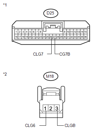
*1 |
Front view of wire harness connector (to Certification ECU (Smart Key ECU Assembly)) |
|
*2 |
Front view of wire harness connector (to Indoor Electrical Key Oscillator (for Rear Floor)) |
| NG | |
REPAIR OR REPLACE HARNESS OR CONNECTOR |
|
|
3. |
INSPECT CERTIFICATION ECU (SMART KEY ECU ASSEMBLY) (INDOOR ELECTRICAL KEY OSCILLATOR SIGNAL OUTPUT) |
|
(a) Reconnect the certification ECU (smart key ECU assembly) connector. |
|
(b) Measure the resistance and check for pulses according to the value(s) in the table below.
Standard Resistance:
|
Tester Connection |
Condition |
Specified Condition |
|---|---|---|
|
D25-15 (E) - Body ground |
Always |
Below 1 Ω |
Standard:
|
Tester Connection |
Condition |
Specified Condition |
|---|---|---|
|
D25-26 (CLG7) - D25-15 (E) |
|
No pulse generation |
|
D25-26 (CLG7) - D25-15 (E) |
|
Pulse generation |
|
D25-27 (CG7B) - D25-15 (E) |
|
No pulse generation |
|
D25-27 (CG7B) - D25-15 (E) |
|
Pulse generation |
|
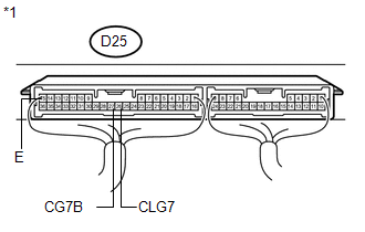
*1 |
Component with harness connected (Certification ECU (Smart Key ECU Assembly)) |
| NG | |
REPLACE CERTIFICATION ECU (SMART KEY ECU ASSEMBLY) |
|
|
4. |
REPLACE INDOOR ELECTRICAL KEY OSCILLATOR (for Rear Floor) |
(a) Replace the indoor electrical key oscillator (for rear floor) (See page
).
|
|
5. |
CHECK DTC OUTPUT |
(a) Clear the DTCs (See page ).
(b) Recheck for DTCs.
OK:
DTC B27A7 is not output.
| OK | |
END (INDOOR ELECTRICAL KEY OSCILLATOR WAS DEFECTIVE) |
| NG | |
REPLACE CERTIFICATION ECU (SMART KEY ECU ASSEMBLY) |
 Open in Rear Floor Electrical Key Oscillator Circuit (B27A6)
DESCRIPTION
The certification ECU (smart key ECU assembly) generates a request signal and
sends it to the indoor electrical key oscillator (for center floor). To detect the
key inside the cabin, ...
 Open in Front Floor Electrical Key Oscillator Circuit (B27A5)
DESCRIPTION
The certification ECU (smart key ECU assembly) generates a request signal and
sends it to the indoor electrical key oscillator (for front floor). To detect the
key inside the cabin, t ...
Other materials about Toyota Venza:
IG Power Supply Voltage Malfunction (C1551)
DESCRIPTION
The power steering ECU distinguishes the ignition switch status as ON or off
through the IG power source circuit.
DTC No.
DTC Detection Condition
Trouble Area
C1551
IG power source ci ...
Installation
INSTALLATION
PROCEDURE
1. INSTALL TIMING CHAIN COVER SUB-ASSEMBLY
(a) Apply a light coat of engine oil to 2 new oil pump gaskets and new
oil hole cover gasket.
(b) Install the 2 new oil pump gas ...
Installation
INSTALLATION
PROCEDURE
1. INSTALL BRAKE PEDAL SUPPORT ASSEMBLY
(a) Install the brake pedal support assembly to the instrument panel
reinforcement with the bolt.
Torque:
19 N·m {195 kgf·cm, 14 ft·lbf}
...

0.168