Toyota Venza: Horn
Components
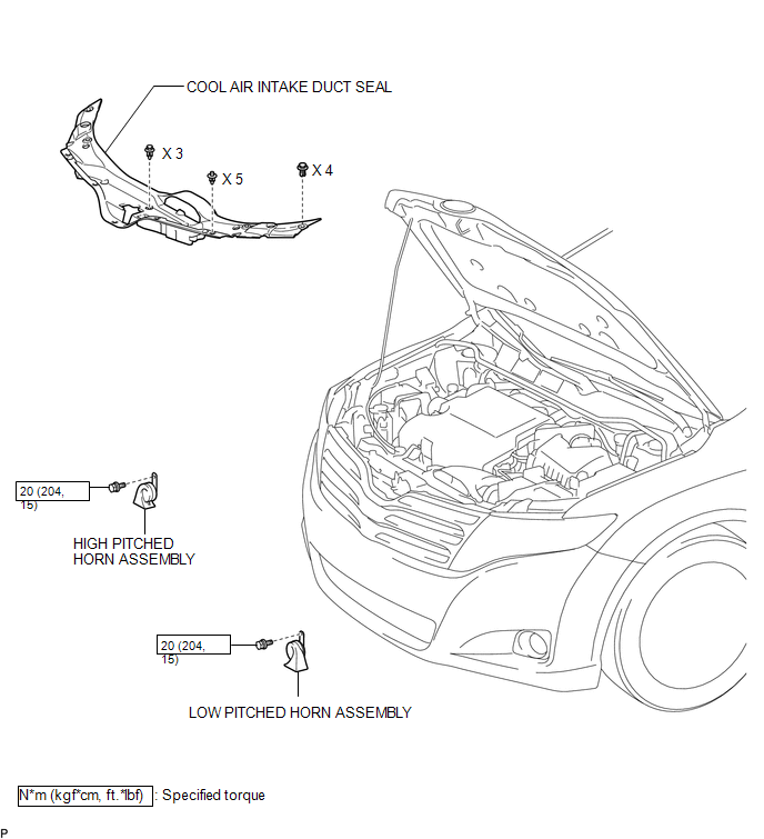
COMPONENTS
ILLUSTRATION
Inspection
INSPECTION
PROCEDURE
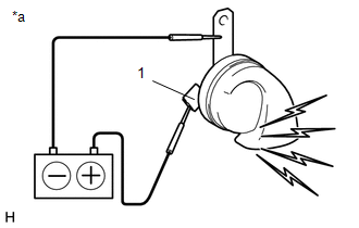
1. INSPECT LOW PITCHED HORN ASSEMBLY
|
(a) Apply battery voltage and check the operation of the low pitched horn assembly according to the table below. OK:
If the result is not as specified, replace the low pitched horn assembly. |
|
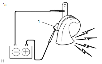
2. INSPECT HIGH PITCHED HORN ASSEMBLY
|
(a) Apply battery voltage and check the operation of the high pitched horn assembly according to the table below. OK:
If the result is not as specified, replace the high pitched horn assembly. |
|
Removal
REMOVAL
PROCEDURE
1. REMOVE COOL AIR INTAKE DUCT SEAL
.gif)
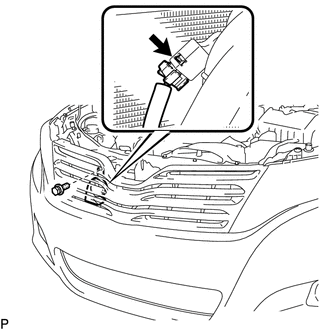
2. REMOVE LOW PITCHED HORN ASSEMBLY
|
(a) Disconnect the connector. |
|
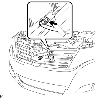
(b) Remove the bolt and low pitched horn assembly.
3. REMOVE HIGH PITCHED HORN ASSEMBLY
|
(a) Disconnect the connector. |
|
(b) Remove the bolt and high pitched horn assembly.
Installation
INSTALLATION
PROCEDURE
1. INSTALL LOW PITCHED HORN ASSEMBLY
(a) Install the low pitched horn assembly with the bolt.
Torque:
20 N·m {204 kgf·cm, 15 ft·lbf}
(b) Connect the connector.
2. INSTALL HIGH PITCHED HORN ASSEMBLY
(a) Install the high pitched horn assembly with the bolt.
Torque:
20 N·m {204 kgf·cm, 15 ft·lbf}
(b) Connect the connector.
3. INSTALL COOL AIR INTAKE DUCT SEAL
.gif)
 Horn
Horn
...
 Horn System
Precaution
PRECAUTION
NOTICE:
When disconnecting the cable from the negative (-) battery terminal, initialize
the following system after the cable is reconnected.
System Name
...
Other materials about Toyota Venza:
Diagnostic Trouble Code Chart
DIAGNOSTIC TROUBLE CODE CHART
HINT:
If a trouble code is displayed during the DTC check, inspect the trouble areas
listed below for that code. For details of the code, refer to the following "See
page".
Power back door system
DTC C ...
Problem Symptoms Table
PROBLEM SYMPTOMS TABLE
HINT:
Use the table below to help determine the cause of problem symptoms. If multiple
suspected areas are listed, the potential causes of the symptoms are listed in order
of probability in the "Suspected Area" column of ...
Installation
INSTALLATION
CAUTION / NOTICE / HINT
HINT:
Use the same procedure for the LH side and RH side.
The following procedure listed is for the LH side.
PROCEDURE
1. INSTALL FRONT LOWER BALL JOINT
(a) Install the front lower ball jo ...

0.1135