Toyota Venza: Interior Light Circuit
DESCRIPTION
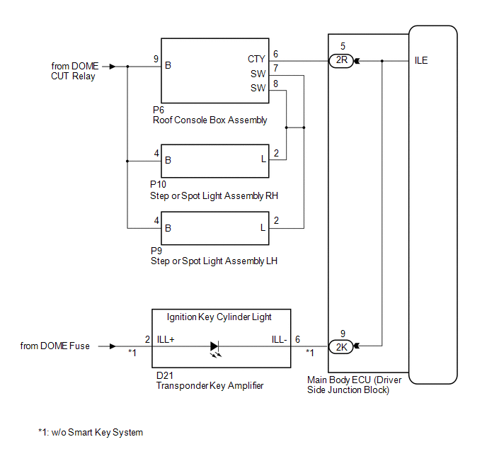
The illuminated entry system controls the roof console box assembly, step or spot light assembly and transponder key amplifier*1.
HINT:
*1: w/o Smart Key System
WIRING DIAGRAM
PROCEDURE
|
1. |
PERFORM ACTIVE TEST USING TECHSTREAM |
(a) Connect the Techstream to the DLC3.
(b) Turn the ignition switch to ON.
(c) Turn the Techstream on.
(d) Enter the following menus: Body Electrical / Main Body / Active Test.
(e) Check that the lights operate.
Main Body|
Tester Display |
Test Part |
Control Range |
Diagnostic Note |
|---|---|---|---|
|
Illuminated Entry System |
Roof console box assembly, step or spot light assembly and transponder key amplifier |
ON/OFF |
Interior light switch is in the DOOR position and all doors are closed. |
OK:
Each light fades in.
| OK | .gif) |
PROCEED TO NEXT SUSPECTED AREA SHOWN IN PROBLEM SYMPTOMS TABLE |
|
.gif)
|
2. |
INSPECT MAIN BODY ECU (DRIVER SIDE JUNCTION BLOCK ASSEMBLY) |
(a) Measure the voltage according to the value(s) in the table below.
 Text in Illustration
|
*1 |
Component with harness connected (Main Body ECU (Driver Side Junction Block Assembly)) |
- |
- |
Standard Voltage:
|
Tester Connection |
Condition |
Specified Condition |
|---|---|---|
|
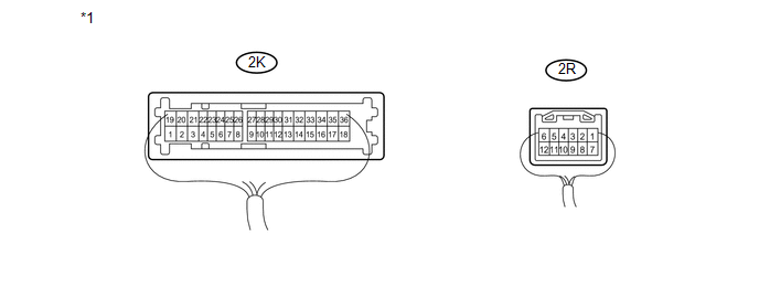
2K-9 - Body ground |
Ignition key cylinder light off |
11 to 14 V |
|
2R-5 - Body ground |
Interior light switch in DOOR position and Interior lights off |
11 to 14 V |
| OK | |
REPLACE MAIN BODY ECU (DRIVER SIDE JUNCTION BLOCK ASSEMBLY) |
| NG | |
REPAIR OR REPLACE HARNESS OR CONNECTOR |
 Door Courtesy Switch Circuit
DESCRIPTION
The main body ECU (driver side junction block assembly) detects the condition
of the door courtesy light switch.
WIRING DIAGRAM
PROCEDURE
1.
READ VALUE USING ...
 Interior Light Auto Cut Circuit
DESCRIPTION
When battery saving control operates while the interior lights are on, the main
body ECU (driver side junction block assembly) opens the DOME CUT relay to turn
off the lights.
WIRING ...
Other materials about Toyota Venza:
Terminals Of Ecu
TERMINALS OF ECU
1. CHECK TIRE PRESSURE WARNING ECU
HINT:
Inspect the connectors from the back side while the connectors are connected.
(a) Disconnect the L14 tire pressure warning antenna and receiver connector.
(b) Measure the voltage according to the ...
Stop Light Switch
Components
COMPONENTS
ILLUSTRATION
Removal
REMOVAL
PROCEDURE
1. REMOVE STOP LIGHT SWITCH ASSEMBLY
(a) Disconnect the connector.
(b) Turn the stop light switch assembly countercl ...
Main Body ECU Communication Stop Mode
DESCRIPTION
Detection Item
Symptom
Trouble Area
Main Body ECU Communication Stop Mode
"Main Body" is not displayed on "CAN Bus Check" screen of the
Techstream.
...

0.1753