Toyota Venza: Installation
INSTALLATION
PROCEDURE
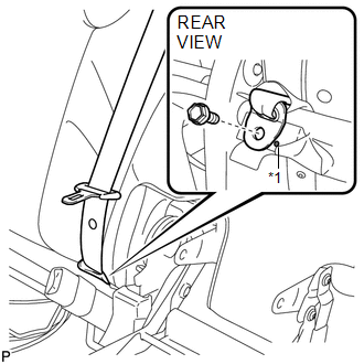
1. INSTALL REAR CENTER SEAT OUTER BELT ASSEMBLY
|
(a) Install the rear center seat outer belt assembly with the bolt and nut. Torque: Bolt : 7.5 N·m {77 kgf·cm, 66 in·lbf} Nut : 42 N·m {428 kgf·cm, 31 ft·lbf} |
|
.png)
2. INSTALL REAR SEATBACK COVER WITH PAD
.gif)
3. INSTALL REAR SEAT CENTER HEADREST SUPPORT RH
4. INSTALL REAR SEAT CENTER HEADREST SUPPORT LH
5. INSTALL REAR SEAT HEADREST SUPPORT RH
6. INSTALL REAR SEAT HEADREST SUPPORT LH
7. INSTALL REAR SEAT SHOULDER BELT COVER
|
(a) Engage the 2 guides and claw, and install the rear seat shoulder cover as shown in the illustration. |
|
.png)
|
(b) Engage the 2 guides as shown in the illustration. |
|
.png)
|
(c) Connect the rear seatback upper lock bezel with the screw. |
|
.png)
8. INSTALL REAR SEATBACK BOARD RH
9. CONNECT REAR CENTER SEAT OUTER BELT ASSEMBLY
|
(a) Connect the rear center seat outer belt with the bolt. Text in Illustration
Torque: 42 N·m {428 kgf·cm, 31 ft·lbf} |
|
10. INSTALL REAR SEAT CUSHION COVER WITH PAD
11. INSTALL REAR SEAT CENTER ARMREST ASSEMBLY
12. INSTALL REAR SEAT RECLINING COVER RH
13. INSTALL CENTER SEAT HINGE COVER RH
14. INSTALL REAR SEAT INNER RECLINING COVER RH
15. INSTALL REAR SEAT RECLINING RELEASE LEVER RH
16. INSTALL SEAT ADJUSTER COVER CAP RH
17. INSTALL REAR SEAT ASSEMBLY RH
18. INSTALL REAR SEAT RECLINING CONTROL CABLE SUB-ASSEMBLY
19. INSTALL REAR SEAT OUTER TRACK BRACKET COVER
20. INSTALL REAR SEAT INNER TRACK BRACKET COVER
21. INSTALL REAR SEAT CENTER HEADREST ASSEMBLY
22. INSTALL REAR SEAT HEADREST ASSEMBLY
 Removal
REMOVAL
PROCEDURE
1. REMOVE REAR SEAT HEADREST ASSEMBLY
2. REMOVE REAR SEAT CENTER HEADREST ASSEMBLY
3. REMOVE REAR SEAT INNER TRACK BRACKET COVER
4. REMOVE REAR SEAT OUTER TRACK BRACKET ...

Other materials about Toyota Venza:
Data Signal Circuit between Navigation Receiver Assembly and Extension Module
DESCRIPTION
The stereo component tuner assembly sends the image data signal to the navigation
receiver assembly via this circuit.
WIRING DIAGRAM
PROCEDURE
1.
CHECK NAVIGATION WIRE
(a) Remove the navigation wire (See pag ...
Installation
INSTALLATION
PROCEDURE
1. INSTALL NO. 2 WINDSHIELD GLASS STOPPER
(a) Using a brush or a sponge, coat the application area of 2 new No. 2 windshield
glass stoppers with Primer G.
NOTICE:
Do not apply too much primer.
Allow the primer to dry f ...
Evaporative Emission System Leak Detection Reference Orifice Low Flow (P043E,P043F,P2401,P2402,P2419)
DTC SUMMARY
DTC No.
Monitoring Item
Malfunction Detection Condition
Trouble Area
Detection Timing
Detection Logic
P043E
Reference orifice clogged
P043E, P ...

0.1218