Toyota Venza: Installation
INSTALLATION
PROCEDURE
1. INSTALL FRONT NO. 1 STABILIZER BAR BUSHING
|
(a) Install the 2 front No. 1 stabilizer bar bushings to the front stabilizer bar as shown in the illustration. Text in Illustration
NOTICE: When installing the front No. 1 stabilizer bar bushings, make sure that the cutout faces the rear of the vehicle. |
|
.png)
2. INSTALL FRONT NO. 2 STABILIZER BRACKET LH
|
(a) Install the front No. 2 stabilizer bracket LH to the front No. 1 stabilizer bar bushing. |
|
.png)
3. INSTALL FRONT NO. 2 STABILIZER BRACKET RH
HINT:
Perform the same procedure as for the LH side.
4. INSTALL FRONT NO. 1 STABILIZER BRACKET LH
(a) Install the front No. 1 stabilizer bracket LH to the front No. 1 stabilizer bar bushing.
5. INSTALL FRONT NO. 1 STABILIZER BRACKET RH
HINT:
Perform the same procedure as for the LH side.
6. TEMPORARILY INSTALL FRONT STABILIZER BAR
(a) Temporarily Install the front stabilizer bar to the vehicle.
NOTICE:
Use wire or an equivalent tool to keep the front stabilizer bar.
7. TEMPORARILY INSTALL STEERING LINK ASSEMBLY
.gif)
8. INSTALL FRONT FRAME ASSEMBLY
for 1AR-FE: (See page )
for 2GR-FE: (See page )
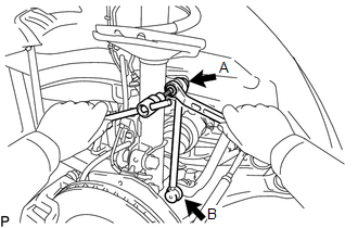
9. INSTALL FRONT STABILIZER LINK ASSEMBLY LH
|
(a) Install the front stabilizer link assembly LH with the 2 nuts. Torque: Nut A : 130 N·m {1326 kgf·cm, 96 ft·lbf} Nut B : 74 N·m {755 kgf·cm, 55 ft·lbf} HINT: If the ball joint turns together with the nut, use a hexagon wrench (6 mm) to hold the stud bolt. |
|
10. INSTALL FRONT STABILIZER LINK ASSEMBLY RH
HINT:
Perform the same procedure as for the LH side.
11. INSTALL FRONT WHEELS
12. INSPECT AND ADJUST FRONT WHEEL ALIGNMENT
(See page )
 Inspection
INSPECTION
PROCEDURE
1. INSPECT FRONT STABILIZER LINK ASSEMBLY
(a) Inspect the turning torque of the ball joint.
(1) Secure the front stabilizer link assembly in a vise using aluminum ...
 Front Stabilizer Bar(for 1ar-fe 2wd)
Components
COMPONENTS
ILLUSTRATION
Inspection
INSPECTION
PROCEDURE
1. INSPECT FRONT STABILIZER LINK ASSEMBLY
(a) Inspect the turning torque of the ball joint.
(1) Secure the ...
Other materials about Toyota Venza:
Actuator Check
ACTUATOR CHECK
1. ACTUATOR CHECK
(a) Start the engine and warm it up.
(b) Perform the indicator check (See page
).
(c) Press the "Recirculation/Fresh" switch to perform the actuator check.
HINT:
Be sure to perform the actuator check after ...
Installation
INSTALLATION
PROCEDURE
1. INSTALL NO. 3 PARKING BRAKE CABLE ASSEMBLY
(a) Install the No. 3 parking brake cable assembly with the bolt and 4 nuts.
Torque:
Nut (A) :
5.4 N·m {55 kgf·cm, 48 in·lbf}
Nut (B) :
6.0 N·m {61 kgf·cm, 53 in·lbf}
Bolt ...
Fail-safe Chart
FAIL-SAFE CHART
1. HID Headlight System
(a) Light Control ECU
(1) The light control ECU stops illuminating the HID headlights when any of the
following abnormalities are detected.
Condition
Content
Open in output si ...

0.1674