Toyota Venza: Front Lower Suspension Arm(when Using The Engine Support Bridge)
Components
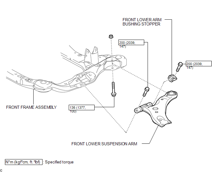
COMPONENTS
ILLUSTRATION
Removal
REMOVAL
CAUTION / NOTICE / HINT
HINT:
- Use the same procedure for the LH side and RH side.
- The following procedure is for the LH side.
PROCEDURE
1. REMOVE FRONT FRAME ASSEMBLY
for 1AR-FE: (See page .gif) )
)
for 2GR-FE: (See page )
2. REMOVE FRONT LOWER SUSPENSION ARM
|
(a) Remove the 3 bolts, nut and front lower suspension arm from the front frame assembly. |
|
.png)
(b) Remove the front lower arm bushing stopper from the front lower suspension arm.
Installation
INSTALLATION
CAUTION / NOTICE / HINT
HINT:
- Use the same procedure for the LH side and RH side.
- The following procedure is for the LH side.
PROCEDURE
1. INSTALL FRONT LOWER SUSPENSION ARM
(a) Install the front lower arm bushing stopper to the front lower suspension arm.
(b) Temporarily tighten the front lower suspension arm to the front frame assembly with the 3 bolts and nut.
|
(c) Tighten the 3 bolts in the order shown in the illustration. Torque: Bolt 1, 2 : 200 N·m {2039 kgf·cm, 147 ft·lbf} Bolt 3 : 135 N·m {1377 kgf·cm, 100 ft·lbf} HINT: Start installing the bolts from the front of the vehicle. |
|
.png)
2. INSTALL FRONT FRAME ASSEMBLY
for 1AR-FE: (See page .gif) )
)
for 2GR-FE: (See page )
 Installation
INSTALLATION
CAUTION / NOTICE / HINT
HINT:
Use the same procedure for the LH side and RH side.
The following procedure is for the LH side.
PROCEDURE
1. INSTALL FRONT LOWER SUSPE ...

Other materials about Toyota Venza:
Front Passenger Side Seat Belt Warning Light Malfunction
DESCRIPTION
The occupant classification ECU detects the state of the front seat inner belt
assembly RH and load sensor when the front passenger side seat is occupied with
the ignition switch ON. If the front passenger side seat belt is not fastened, the
...
Relay
On-vehicle Inspection
ON-VEHICLE INSPECTION
PROCEDURE
1. FAN NO. 1 RELAY
(a) Remove the relay from the engine room relay block.
(b) Measure the resistance according to the value(s) in the table b ...
Installing child restraints
Follow the child restraint system manufacturer’s instructions. Firmly secure
child restraints to the rear seats using the LATCH anchors or a seat belt. Attach
the top tether strap when installing a child restraint.
The lap/shoulder belt can be used if y ...

0.1732