Toyota Venza: Terminals Of Ecm
TERMINALS OF ECM
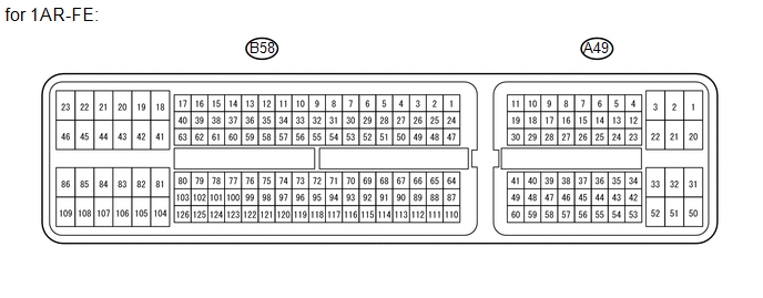
1. CHECK ECM
|
Terminal No. (Symbol) |
Wiring Color |
Terminal Description |
Condition |
Specified Condition |
|---|---|---|---|---|
|
A49-7 (TC) - B58-104 (E1) |
V - BR |
Terminal TC of DLC3 |
Ignition switch ON |
11 to 14 V |
|
A49-7 (TC) - B58-104 (E1) |
V - BR |
Terminal TC of DLC3 |
Terminals TC and CG of DLC3 connected |
Below 1 V |
|
A49-29 (STP) - B58-104 (E1) |
G - BR |
Stop light switch signal |
Brake pedal depressed |
7.5 to 14 V |
|
A49-29 (STP) - B58-104 (E1) |
G - BR |
Stop light switch signal |
Brake pedal released |
Below 1 V |
|
A49-39 (ST1-) - B58-104 (E1) |
V - BR |
Stop light switch signal |
Ignition switch ON Brake pedal depressed |
Below 1 V |
|
A49-39 (ST1-) - B58-104 (E1) |
V - BR |
Stop light switch signal |
Ignition switch ON Brake pedal released |
7.5 to 14 V |
|
A49-40 (CCS) - B58-104 (E1) |
P - BR |
Cruise control main switch signal |
Ignition switch ON |
11 to 14 V |
|
A49-40 (CCS) - B58-104 (E1) |
P - BR |
Cruise control main switch signal |
CANCEL switch on |
6.6 to 10.1 V |
|
A49-40 (CCS) - B58-104 (E1) |
P - BR |
Cruise control main switch signal |
- SET switch on |
4.5 to 7.1 V |
|
A49-40 (CCS) - B58-104 (E1) |
P - BR |
Cruise control main switch signal |
+ RES switch on |
2.3 to 4.0 V |
|
A49-40 (CCS) - B58-104 (E1) |
P - BR |
Cruise control main switch signal |
MAIN switch on |
Below 1 V |
|
Terminal No. (Symbol) |
Wiring Color |
Terminal Description |
Condition |
Specified Condition |
|---|---|---|---|---|
|
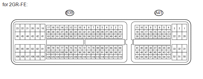
A41-16 (TC) - B39-81 (E1) |
V - W |
Terminal TC of DLC3 |
Ignition switch ON |
11 to 14 V |
|
A41-16 (TC) - B39-81 (E1) |
V - W |
Terminal TC of DLC3 |
Terminals TC and CG of DLC3 connected |
Below 1 V |
|
A41-36 (STP) - B39-81 (E1) |
G - W |
Stop light switch signal |
Brake pedal depressed |
7.5 to 14 V |
|
A41-36 (STP) - B39-81 (E1) |
G - W |
Stop light switch signal |
Brake pedal released |
Below 1 V |
|
A41-35 (ST1-) - B39-81 (E1) |
V - W |
Stop light switch signal |
Ignition switch ON Brake pedal depressed |
Below 1 V |
|
A41-35 (ST1-) - B39-81 (E1) |
V - W |
Stop light switch signal |
Ignition switch ON Brake pedal released |
7.5 to 14 V |
|
A41-45 (CCS) - B39-81 (E1) |
P - W |
Cruise control main switch signal |
Ignition switch ON |
11 to 14 V |
|
A41-45 (CCS) - B39-81 (E1) |
P - W |
Cruise control main switch signal |
CANCEL switch on |
6.6 to 10.1 V |
|
A41-45 (CCS) - B39-81 (E1) |
P - W |
Cruise control main switch signal |
- SET switch on |
4.5 to 7.1 V |
|
A41-45 (CCS) - B39-81 (E1) |
P - W |
Cruise control main switch signal |
+ RES switch on |
2.3 to 4.0 V |
|
A41-45 (CCS) - B39-81 (E1) |
P - W |
Cruise control main switch signal |
MAIN switch on |
Below 1 V |
 Diagnosis System
DIAGNOSIS SYSTEM
1. DESCRIPTION
The ECM controls the cruise control system of the vehicle. The data and DTCs
relating to the cruise control system can be read from the DLC3 of the vehicle.
If ei ...
 Dtc Check / Clear
DTC CHECK / CLEAR
1. CHECK DTC
(a) Connect the Techstream to the DLC3.
(b) Turn the ignition switch to ON.
(c) Turn the Techstream on.
(d) Enter the following menus: Powertrain / Cruise Control / ...
Other materials about Toyota Venza:
IG Power Supply Voltage Malfunction (C1551)
DESCRIPTION
The power steering ECU distinguishes the ignition switch status as ON or off
through the IG power source circuit.
DTC No.
DTC Detection Condition
Trouble Area
C1551
IG power source ci ...
Removal
REMOVAL
PROCEDURE
1. PRECAUTION
NOTICE:
After turning the ignition switch off, waiting time may be required before disconnecting
the cable from the negative (-) battery terminal. Therefore, make sure to read the
disconnecting the cable from the negativ ...
Diagnosis System
DIAGNOSIS SYSTEM
1. DESCRIPTION
(a) The transponder key ECU assembly controls the vehicle's immobiliser system
functions. Immobiliser system data and Diagnostic Trouble Code (DTC) can be read
through the vehicle's Data Link Connector 3 (DLC3).
I ...

0.1258