Toyota Venza: Inspection
INSPECTION
PROCEDURE
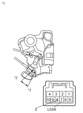
1. INSPECT FRONT DOOR LOCK ASSEMBLY LH
(a) Check the operation of the door lock motor.
|
(1) Apply battery voltage and check the operation of the door lock motor. OK:
If the result is not as specified, replace the front door lock assembly LH. |
|
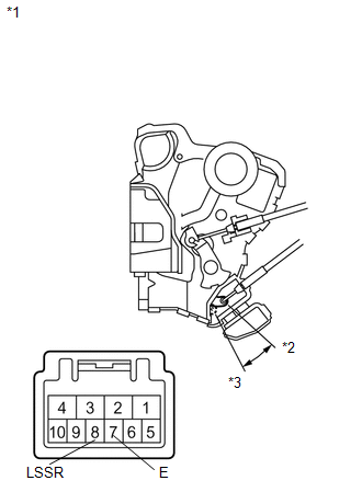
(b) Check the operation of the door unlock detection switch.
|
(1) Measure the resistance according to the value(s) in the table below. Standard Resistance:
If the result is not as specified, replace the front door lock assembly LH. |
|
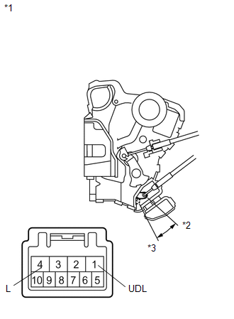
(c) Check the operation of the door key lock and unlock switch.
|
(1) Measure the resistance according to the value(s) in the table below. Standard Resistance:
If the result is not as specified, replace the front door lock assembly LH. |
|
2. INSPECT FRONT DOOR LOCK ASSEMBLY RH
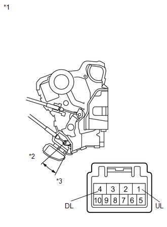
(a) Check the operation of the door lock motor.
|
(1) Apply battery voltage and check the operation of the door lock motor. OK:
If the result is not as specified, replace the front door lock assembly RH. |
|
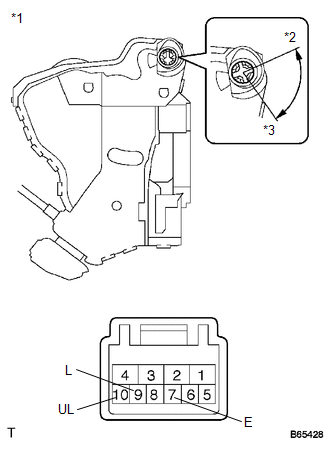
(b) Check the operation of the door unlock detection switch.
|
(1) Measure the resistance according to the value(s) in the table below. Standard Resistance:
If the result is not as specified, replace the front door lock assembly RH. |
|
 Removal
REMOVAL
PROCEDURE
1. DISCONNECT CABLE FROM NEGATIVE BATTERY TERMINAL
CAUTION:
Wait at least 90 seconds after disconnecting the cable from the negative (-)
battery terminal to disable the SRS sys ...
 Installation
INSTALLATION
PROCEDURE
1. INSTALL FRONT DOOR LOCK ASSEMBLY
NOTICE:
When reusing the removed front door lock assembly, replace the door
lock wiring harness seal on the connector with a ...
Other materials about Toyota Venza:
Precaution
PRECAUTION
1. PRECAUTION FOR DISCONNECTING CABLE FROM NEGATIVE BATTERY TERMINAL
NOTICE:
When disconnecting the cable from the negative (-) battery terminal, initialize
the following systems after the terminal is reconnected.
System Name
...
Torque Converter Clutch Pressure Control Solenoid Performance (Shift Solenoid
Valve SLU) (P2757)
SYSTEM DESCRIPTION
The TCM uses the signals from the throttle position sensor, air-flow meter, turbine
(input) speed sensor, output speed sensor and crankshaft position sensor to monitor
the engagement condition of the lock-up clutch.
The TCM compares ...
VC Output Circuit
DESCRIPTION
The ECM constantly generates 5 V of power from battery voltage supplied to the
+B (BATT) terminal to operate the microprocessor. The ECM also provides this power
to the sensors through the VC output circuit.
When the VC circuit is short-cir ...

0.1462