Toyota Venza: Power Back Door Warning Buzzer
Components
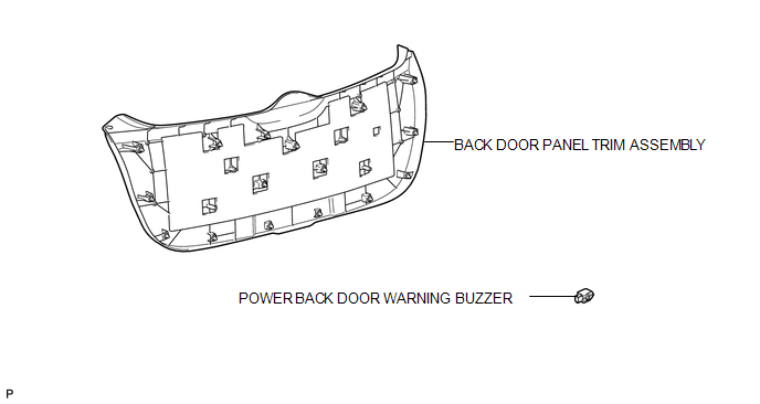
COMPONENTS
ILLUSTRATION
Inspection
INSPECTION
PROCEDURE
1. INSPECT POWER BACK DOOR WARNING BUZZER
|
(a) Measure the resistance according to the value(s) in the table below. HINT: If battery voltage is applied directly to the buzzer, the buzzer will not sound. Standard Resistance:
If the result is not as specified, replace the power back door warning buzzer. |
|
.png)
Removal
REMOVAL
PROCEDURE
1. REMOVE BACK DOOR PANEL TRIM ASSEMBLY
.gif)
2. REMOVE POWER BACK DOOR WARNING BUZZER
|
(a) Disconnect the connector. |
|
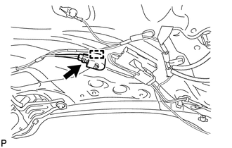
(b) Disengage the clamp to remove the power back door warning buzzer.
Installation
INSTALLATION
PROCEDURE
1. INSTALL POWER BACK DOOR WARNING BUZZER
|
(a) Engage the clamp to install the power back door warning buzzer. |
|
.png)
(b) Connect the connector.
2. INSTALL BACK DOOR PANEL TRIM ASSEMBLY
.gif)
 Power Back Door Touch Sensor
Components
COMPONENTS
ILLUSTRATION
Removal
REMOVAL
PROCEDURE
1. REMOVE UPPER BACK WINDOW PANEL TRIM
2. REMOVE BACK DOOR PANEL TRIM ASSEMBLY
3. DISCONNECT POWER BACK DOOR ROD (for L ...
 Rear Door
...
Other materials about Toyota Venza:
Air Fuel Ratio Sensor
Components
COMPONENTS
ILLUSTRATION
Removal
REMOVAL
PROCEDURE
1. REMOVE NO. 1 ENGINE COVER SUB-ASSEMBLY
2. REMOVE COOL AIR INTAKE DUCT SEAL
3. REMOVE INLET AIR CLEANER ASSEMBLY
4. REMOVE NO. 1 EXHAUST MANIFOLD HEAT INSULATOR
5. REMOV ...
If you think something is wrong
If you notice any of the following symptoms, your vehicle probably needs adjustment
or repair. Contact your Toyota dealer as soon as possible.
- Visible symptoms
• Fluid leaks under the vehicle
(Water dripping from the air conditioning after use i ...
Jam Protection Function Activates During Power Back Door Operation
DESCRIPTION
When the jam protection function activates during power back door operation,
one of the following may be the cause: 1) improper fit of back door, or a foreign
object is stuck in the back door, 2) malfunctioning power back door touch sensor
c ...

0.1294