Toyota Venza: Front Passenger Side Power Mirror cannot be Adjusted with Power Mirror Switch
SYSTEM DESCRIPTION
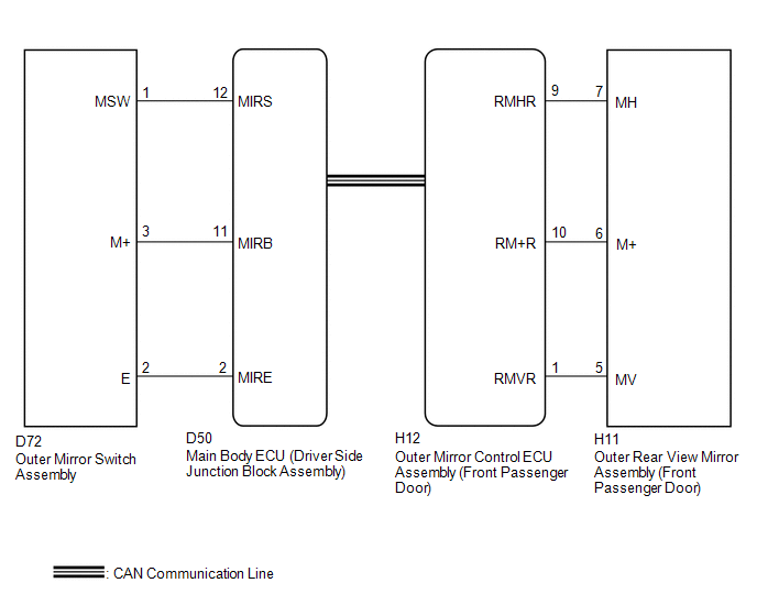
When the mirror adjust switch is operated, the main body ECU (driver side junction block assembly) detects the switch operation and sends the mirror adjust switch signal to the outer mirror control ECU assembly (front passenger door) via CAN communication. On receiving the signal, the outer mirror control ECU assembly (front passenger door) operates the vertical and horizontal mirror motors, which are built into the outer rear view mirror assembly (front passenger door), to adjust the mirror surface position.
WIRING DIAGRAM
PROCEDURE
|
1. |
CHECK CAN COMMUNICATION SYSTEM |
(a) Use the Techstream to check if the CAN communication system is functioning
normally (See page .gif) ).
).
OK:
CAN communication DTC is not output.
| NG | .gif) |
GO TO CAN COMMUNICATION SYSTEM (DIAGNOSTIC TROUBLE CODE CHART) |
|
.gif)
|
2. |
READ VALUE USING TECHSTREAM (OUTER MIRROR SWITCH ASSEMBLY) |
(a) Connect the Techstream to the DLC3.
(b) Turn the ignition switch ON.
(c) Turn the Techstream on.
(d) Enter the following menus: Body Electrical / Main Body / Data List.
(e) Read the Data List according to the display on the Techstream.
Main Body|
Tester Display |
Measurement Item/Range |
Normal Condition |
Diagnostic Note |
|---|---|---|---|
|
Mirror Selection SW (R) |
Mirror select switch signal for RH mirror / ON or OFF |
ON: Mirror select switch in R position OFF: Mirror select switch off or in L position |
- |
|
Mirror Position SW (R) |
Mirror adjust switch signal (Right) / ON or OFF |
ON: Mirror adjust switch pressed right OFF: Mirror adjust switch not pressed right |
Check with the mirror select switch in the R position |
|
Mirror Position SW (L) |
Mirror adjust switch signal (Left) / ON or OFF |
ON: Mirror adjust switch pressed left OFF: Mirror adjust switch not pressed left |
Check with the mirror select switch in the R position |
|
Mirror Position SW (Up) |
Mirror adjust switch signal (Up) / ON or OFF |
ON: Mirror adjust switch pressed up OFF: Mirror adjust switch not pressed up |
Check with the mirror select switch in the R position |
|
Mirror Position SW (Dwn) |
Mirror adjust switch signal (Down) / ON or OFF |
ON: Mirror adjust switch pressed down OFF: Mirror adjust switch not pressed down |
Check with the mirror select switch in the R position |
OK:
On the Techstream screen, ON or OFF is displayed for each item according to the table above.
| NG | |
GO TO STEP 6 |
|
|
3. |
PERFORM ACTIVE TEST USING TECHSTREAM (POWER MIRROR CONTROL FUNCTION) |
(a) Enter the following menus: Body Electrical / Mirror R / Active Test.
(b) Perform the Active Test according to the display on the Techstream.
Mirror R|
Tester Display |
Test Part |
Control Range |
Diagnostic Note |
|---|---|---|---|
|
Mirror Up/Down |
Mirror vertical operation |
Up / Down |
|
|
Mirror Right/Left |
Mirror horizontal operation |
Right / Left |
|
OK:
Power mirror operation is normal.
| OK | |
REPLACE OUTER MIRROR CONTROL ECU ASSEMBLY (FRONT PASSENGER DOOR) |
|
|
4. |
INSPECT OUTER REAR VIEW MIRROR ASSEMBLY (FRONT PASSENGER DOOR) |
|
(a) Remove the outer rear view mirror assembly (front passenger door)
(See page (1) Apply battery voltage and check the operation of the outer rear view mirror assembly (front passenger door). OK:
|
|
| NG | |
REPLACE OUTER REAR VIEW MIRROR ASSEMBLY (FRONT PASSENGER DOOR) |
|
|
5. |
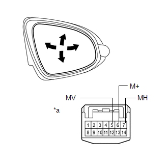
CHECK HARNESS AND CONNECTOR (OUTER REAR VIEW MIRROR ASSEMBLY (FRONT PASSENGER DOOR) - OUTER MIRROR CONTROL ECU ASSEMBLY (FRONT PASSENGER DOOR)) |
(a) Disconnect the H12 connector from the outer rear view mirror assembly (front passenger door).
(b) Disconnect the H11 connector from the outer mirror control ECU assembly (front passenger door).
(c) Measure the resistance according to the value(s) in the table below.
Standard Resistance:
|
Tester Connection |
Condition |
Specified Condition |
|---|---|---|
|
H12-9 (RMHR) - H11-7 (MH) |
Always |
Below 1 Ω |
|
H12-10 (RM+R) - H11-6 (M+) |
Always |
Below 1 Ω |
|
H12-1 (RMVR) - H11-5 (MV) |
Always |
Below 1 Ω |
|
H12-9 (RMHR) - Body ground |
Always |
10 kΩ or higher |
|
H12-10 (RM+R) - Body ground |
Always |
10 kΩ or higher |
|
H12-1 (RMVR) - Body ground |
Always |
10 kΩ or higher |
| OK | |
REPLACE OUTER MIRROR CONTROL ECU ASSEMBLY (FRONT PASSENGER DOOR) |
| NG | |
REPAIR OR REPLACE HARNESS OR CONNECTOR |
|
6. |
INSPECT OUTER MIRROR SWITCH ASSEMBLY |
|
(a) Remove the outer mirror switch assembly (See page
|
|
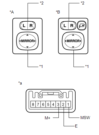
(b) Measure the resistance according to the value(s) in the table below.
Standard Resistance:
|
Tester Connection |
Condition |
Specified Condition |
|---|---|---|
|
3 (M+) - 2 (E) |
Mirror adjust switch pressed up |
90 to 110 Ω |
|
Mirror adjust switch pressed down |
437 to 503 Ω |
|
|
Mirror adjust switch pressed left |
744 to 856 Ω |
|
|
Mirror adjust switch pressed right |
225 to 275 Ω |
|
|
1 (MSW) - 2 (E) |
Mirror select switch R |
Below 10 Ω |
|
Mirror select switch L |
90 to 110 Ω |
|
|
Mirror select switch off |
10 kΩ or higher |
|
*A |
w/o Retract Mirror |
|
*B |
w/ Retract Mirror |
|
*1 |
Mirror Adjust Switch |
|
*2 |
Mirror Select Switch |
|
*a |
Component without harness connected (Outer Mirror Switch Assembly) |
| NG | |
REPLACE OUTER MIRROR SWITCH ASSEMBLY |
|
|
7. |
CHECK HARNESS AND CONNECTOR (OUTER MIRROR SWITCH - MAIN BODY ECU (DRIVER SIDE JUNCTION BLOCK ASSEMBLY)) |
(a) Disconnect the D72 connector from the outer mirror switch assembly.
(b) Disconnect the D50 connector from the main body ECU (driver side junction block assembly).
(c) Measure the resistance according to the value(s) in the table below.
Standard Resistance:
|
Tester Connection |
Condition |
Specified Condition |
|---|---|---|
|
D72-2 (E) - D50-2 (MIRE) |
Always |
Below 1 Ω |
|
D72-3 (M+) - D50-11 (MIRB) |
Always |
Below 1 Ω |
|
D72-1 (MSW) - D50-12 (MIRS) |
Always |
Below 1 Ω |
|
D72-2 (E) - Body ground |
Always |
10 kΩ or higher |
|
D72-3 (M+) - Body ground |
Always |
10 kΩ or higher |
|
D72-1 (MSW) - Body ground |
Always |
10 kΩ or higher |
| OK | |
REPLACE MAIN BODY ECU (DRIVER SIDE JUNCTION BLOCK ASSEMBLY) |
| NG | |
REPAIR OR REPLACE HARNESS OR CONNECTOR |
 Driver Side Power Mirror cannot be Adjusted with Power Mirror Switch
SYSTEM DESCRIPTION
When the mirror adjust switch is operated, the main body ECU (driver side junction
block assembly) detects the switch operation and sends the mirror adjust switch
signal to the ...
 Power Mirror cannot be Adjusted with Power Mirror Switch
SYSTEM DESCRIPTION
The main body ECU (driver side junction block assembly) detects the mirror adjust
switch status and sends the signal to the outer mirror control ECU assembly via
CAN communicat ...
Other materials about Toyota Venza:
How To Proceed With Troubleshooting
CAUTION / NOTICE / HINT
HINT:
Use this procedure to troubleshoot the theft deterrent system.
*: Use the Techstream.
PROCEDURE
1.
VEHICLE BROUGHT TO WORKSHOP
NEXT
...
Removal
REMOVAL
PROCEDURE
1. DISCONNECT CABLE FROM NEGATIVE BATTERY TERMINAL
CAUTION:
Wait at least 90 seconds after disconnecting the cable from the negative (-)
battery terminal to disable the SRS system (See page
).
NOTICE:
When disconnecting the cable, s ...
Problem Symptoms Table
PROBLEM SYMPTOMS TABLE
HINT:
Use the table below to help determine the cause of problem symptoms. If multiple
suspected areas are listed, the potential causes of the symptoms are listed in order
of probability in the "Suspected Area" column of ...

0.1135