Toyota Venza: Terminals Of Ecu
TERMINALS OF ECU
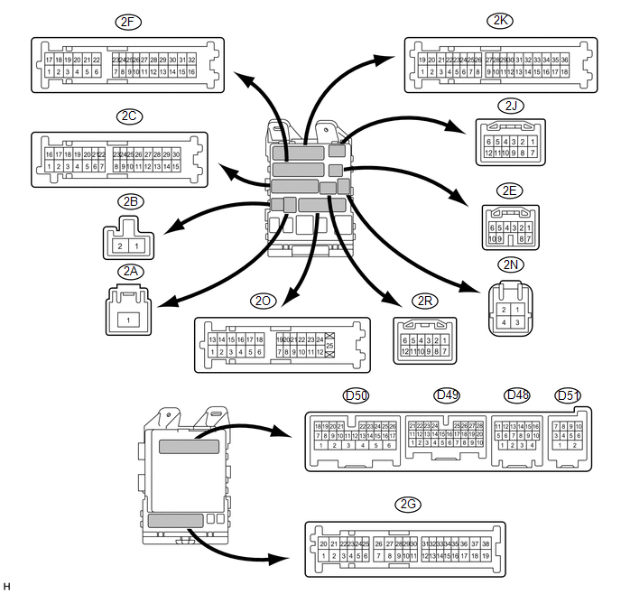
1. CHECK MAIN BODY ECU (DRIVER SIDE JUNCTION BLOCK ASSEMBLY)
(a) Disconnect the main body ECU (driver side junction block assembly) connectors.
(b) Measure the resistance and voltage according to the value(s) in the table below.
|
Tester Connection |
Wiring Color |
Terminal Description |
Condition |
Specified Condition |
|---|---|---|---|---|
|
D49-7 (RCTY) - Body ground |
GR - Body ground |
Rear courtesy light switch RH input |
Rear door RH closed (OFF) → open (ON) |
10 kΩ or higher → Below 1 Ω |
|
D49-21 (PCTY) - Body ground |
V - Body ground |
Passenger side courtesy light switch input |
Passenger side door closed (OFF) → open (ON) |
10 kΩ or higher → Below 1 Ω |
|
D49-25 (BCTY) - Body ground |
GR - Body ground |
Back door courtesy light switch input |
Back door closed (OFF) → open (ON) |
10 kΩ or higher → Below 1 Ω |
|
D50-16 (HCTY) - Body ground |
BE - Body ground |
Security courtesy switch |
Engine hood closed (OFF) → open (ON) |
10 kΩ or higher → Below 1 Ω |
|
D50-24 (DCTY) - Body ground |
V - Body ground |
Driver side door courtesy light switch input |
Driver side door closed (OFF) → open (ON) |
10 kΩ or higher → Below 1 Ω |
|
2A-1 (ACC) - Body ground |
B - Body ground |
Ignition power supply (ACC signal) |
Engine switch on (ACC) → OFF |
11 to 14 V → Below 1 V |
|
2A-1 (IG) - Body ground |
B - Body ground |
Ignition power supply (IG signal) |
Engine switch on (IG) → OFF |
11 to 14 V → Below 1 V |
|
2C-30 (ALTB) - Body ground |
BR - Body ground |
+B (power system alternator system) power supply |
Always |
11 to 14 V |
|
2F-16 (GND1) - Body ground |
W-B - Body ground |
Ground |
Always |
Below 1 Ω |
|
2C-24 (BECU) - Body ground |
L - Body ground |
+B power supply |
Always |
11 to 14 V |
|
2C-24 (BECU) - Body ground |
L - Body ground |
+B power supply |
Always |
11 to 14 V |
|
2O-19 (LCTY) - Body ground |
R - Body ground |
Rear courtesy light switch LH input |
Rear door LH closed (OFF) → open (ON) |
10 kΩ or higher → Below 1 Ω |
If the result is not as specified, there may be a malfunction in the wire harness.
HINT:
Measure values on the wire harness side with the connectors disconnected.
(c) Reconnect the main body ECU (driver side junction block assembly) connectors.
(d) Measure the voltage according to the value(s) in the table below.
|
Tester Connection |
Wiring Color |
Terminal Description |
Condition |
Specified Condition |
|---|---|---|---|---|
|
D48-4 (HAZ) - Body ground |
G - Body ground |
Turn signal flasher relay signal |
System in alarm sounding state |
Below 1 V |
|
D51-4 (IND) - Body ground |
SB - Body ground |
Security indicator output |
Security indicator on (It lights up only in arming preparation state or alarm sounding state. It flashes when immobiliser is operating.) |
3 to 6 V |
|
D51-6 (SH) - Body ground |
BR - Body ground |
Security horn drive |
Security horn sounding |
Pulse generation (Below 1 V ← → 12 V) |
|
2C-25 (HORN) - Body ground |
R - Body ground |
Vehicle horn drive |
Vehicle horn sounding (Theft deterrent system in alarm sounding state) |
Pulse generation (Below 1 V ← → 12 V) |
If the result is not as specified, the main body ECU (driver side junction block assembly) may have a malfunction.
 Problem Symptoms Table
PROBLEM SYMPTOMS TABLE
HINT:
Use the table below to help determine the cause of problem symptoms.
If multiple suspected areas are listed, the potential causes of the symptoms
are lis ...
 Data List / Active Test
DATA LIST / ACTIVE TEST
1. DATA LIST
HINT:
Using the Techstream to read the Data List allows the values or states of switches,
sensors, actuators and other items to be read without removing any p ...
Other materials about Toyota Venza:
Removal
REMOVAL
PROCEDURE
1. REMOVE ROOF DRIP CENTER SIDE FINISH MOULDING (w/o Sliding Roof)
(a) Put protective tape around the roof drip center side finish moulding.
Text in Illustration
*1
Protective Tape
...
Terminals Of Ecu
TERMINALS OF ECU
1. POWER WINDOW REGULATOR MASTER SWITCH ASSEMBLY
(a) Disconnect the I6 power window regulator master switch assembly connector.
(b) Measure the voltage and resistance according to the value(s) in the table
below.
HINT:
Measure the val ...
Abnormal Temperature Inside ID1 Tire (C2165/65-C2168/68)
DESCRIPTION
Each tire pressure warning valve and transmitter measures the tire internal temperature
as well as tire pressure, and transmits the information to the tire pressure warning
ECU along with the transmitter ID. If the measured temperature is out ...

0.1605