Toyota Venza: Driver Side Power Window does not Operate with Power Window Master Switch
DESCRIPTION
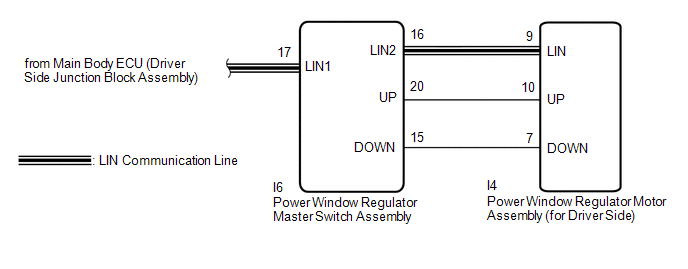
When the engine is running or the ignition switch is ON, the power window regulator motor assembly (for driver side) is operated by the power window regulator master switch assembly. The power window regulator motor assembly (for driver side) has motor, regulator, and ECU functions.
HINT:
If the pulse sensor built into the power window regulator motor assembly (for driver side) malfunctions, the power window control system enters fail-safe mode. The remote up/down and auto up/down functions cannot be operated during fail-safe mode. However, the power window can be closed by holding the power window regulator master switch assembly at the auto up position, and opened manually by pushing down the power window regulator master switch assembly.
WIRING DIAGRAM
CAUTION / NOTICE / HINT
NOTICE:
- The power window control system uses a multiplex communication system
(LIN communication system). Inspect the communication function by following
How to Proceed with Troubleshooting (See page
.gif) ). Troubleshoot the power window control
). Troubleshoot the power window control
system after confirming that the communication system is functioning properly. - When the power window regulator motor assembly (for driver side) is reinstalled or replaced, the power window control system must be initialized.
- After a door glass or a door glass run has been replaced, the jam protection
function may operate unexpectedly when the auto up function is used. In
such cases, the auto up function can be reinitialized by repeating the following
operations at least 5 times:
- Close the power window by fully pulling up the power window regulator master switch assembly and holding it at the auto up position.
- Open the power window by fully pushing down the power window regulator master switch assembly.
- When the ECU determines that the power window regulator motor assembly (for driver side) has a malfunction, DTC B2311 is set.
PROCEDURE
|
1. |
READ VALUE USING TECHSTREAM (Main Body) |
(a) Connect the Techstream to the DLC3.
(b) Turn the ignition switch to ON.
(c) Turn the Techstream on.
(d) Enter the following menus: Body Electrical / Main Body / Data List.
(e) Read the Data List according to the display on the Techstream.
Main Body (Main Body ECU (Driver Side Junction Block Assembly))|
Tester Display |
Measurement Item/Range |
Normal Condition |
Diagnostic Note |
|---|---|---|---|
|
Communication D-Door Motor |
Connection status between power window regulator motor (for driver side) and main body ECU (driver side junction block assembly) / OK or STOP |
OK: Normal communication STOP: Communication stopped |
- |
OK:
On the Techstream screen, OK is displayed.
| NG | .gif) |
GO TO LIN COMMUNICATION SYSTEM (Proceed to How to Proceed with Troubleshooting) |
|
.gif)
|
2. |
READ VALUE USING TECHSTREAM (D-Door Motor) |
(a) Enter the following menus: Body Electrical / D-Door Motor / Data List.
(b) Read the Data List according to the display on the Techstream.
D-Door Motor (Power Window Regulator Motor Assembly (for Driver Side))|
Tester Display |
Measurement Item/Range |
Normal Condition |
Diagnostic Note |
|---|---|---|---|
|
D Door P/W Up SW |
Driver side power window manual up switch signal / ON or OFF |
ON: Driver door power window manual up switch operated OFF: Driver door power window manual up switch not operated |
- |
|
D Door P/W Down SW |
Driver side power window manual down switch signal / ON or OFF |
ON: Driver door power window manual down switch operated OFF: Driver door power window manual down switch not operated |
- |
OK:
On the Techstream screen, ON or OFF is displayed accordingly.
| NG | |
GO TO STEP 4 |
|
|
3. |
PERFORM ACTIVE TEST USING TECHSTREAM (D-Door Motor) |
(a) Enter the following menus: Body Electrical / D-Door Motor / Active Test.
(b) Perform the Active Test according to the display on the Techstream.
D-Door Motor (Power Window Regulator Motor Assembly (for Driver Side))|
Tester Display |
Test Part |
Control Range |
Diagnostic Note |
|---|---|---|---|
|
Power Window |
Power window |
OFF / UP / DOWN |
- |
OK:
Driver side power window operates normally.
CAUTION:
Be careful to avoid injuries as this test causes vehicle parts to move. During the Active Test, the jam protection function will not operate.
| OK | |
REPLACE MAIN BODY ECU (DRIVER SIDE JUNCTION BLOCK ASSEMBLY) |
| NG | |
REPLACE POWER WINDOW REGULATOR MOTOR ASSEMBLY (for Driver Side) |
|
4. |
CHECK HARNESS AND CONNECTOR (MASTER SWITCH - DRIVER SIDE MOTOR) |
(a) Disconnect the power window regulator master switch assembly connector.
(b) Disconnect the power window regulator motor assembly (for driver side) connector.
(c) Measure the resistance according to the value(s) in the table below.
Standard Resistance:
|
Tester Connection |
Condition |
Specified Condition |
|---|---|---|
|
I6-20 (UP) - I4-10 (UP) |
Always |
Below 1 Ω |
|
I6-15 (DOWN) - I4-7 (DOWN) |
Always |
Below 1 Ω |
|
I6-20 (UP) - Body ground |
Always |
10 kΩ or higher |
|
I6-15 (DOWN) - Body ground |
Always |
10 kΩ or higher |
|
I4-10 (UP) - Body ground |
Always |
10 kΩ or higher |
|
I4-7 (DOWN) - Body ground |
Always |
10 kΩ or higher |
|
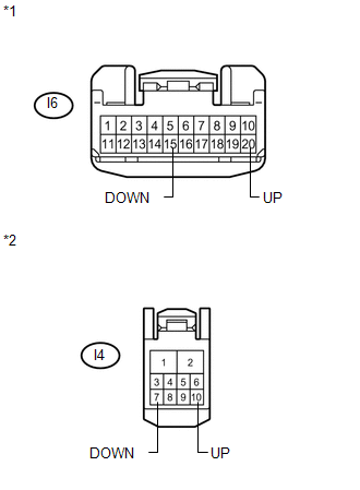
*1 |
Front view of wire harness connector (to Power Window Regulator Master Switch Assembly) |
|
*2 |
Front view of wire harness connector (to Power Window Regulator Motor Assembly (for Driver Side)) |
| NG | |
REPAIR OR REPLACE HARNESS OR CONNECTOR |
|
|
5. |
REPLACE POWER WINDOW REGULATOR MASTER SWITCH ASSEMBLY |
(a) Replace the power window regulator master switch assembly (See page
).
|
|
6. |
CHECK MANUAL UP / DOWN FUNCTION (for Driver Side) |
(a) Check that the driver side door power window moves when the manual up/down
function of the power window regulator master switch assembly is operated (See page
).
OK:
Driver side manual up/down function is normal.
| OK | |
END (POWER WINDOW REGULATOR MASTER SWITCH WAS DEFECTIVE) |
| NG | |
REPLACE POWER WINDOW REGULATOR MOTOR ASSEMBLY (for Driver Side) |
 Remote Up / Down Function does not Operate
DESCRIPTION
When the ignition switch is ON, the power window regulator master switch assembly
sends remote up/down signals to each power window regulator motor assembly via the
LIN communication ...
 Front Passenger Side Power Window does not Operate with Front Passenger Side
Power Window Switch
Front Passenger Side Power Window does not Operate with Front Passenger Side
Power Window Switch
DESCRIPTION
When the engine is running or the ignition switch is ON, the power window regulator
motor assembly (for front passenger side) is operated by the power window regulator
switch assembly ...
Other materials about Toyota Venza:
Removal
REMOVAL
CAUTION / NOTICE / HINT
NOTICE:
Do not remove the steering angle sensor from the spiral cable.
HINT:
The steering angle sensor is a component of the spiral with sensor cable sub-assembly.
If the steering angle sensor malfunctions, replace the sp ...
Head restraints
Head restraints are provided for all seats.
► Front and rear outboard seats
Vertical adjustment 1. Up
Pull the head restraint up.
2. Down
Push the head restraints down while pressing the lock release button.
► Rear center seat (fabric seat) ...
Intake Manifold Runner Position Sensor / Switch Circuit (Bank 1) (P2014,P2016,P2017)
DESCRIPTION
The tumble control valve position sensor is a non-contact type sensor.
The position sensor measures the opening angle of the tumble control valve. The
sensor is reliable and accurate, as it is electrically controlled by Hall elements.
...

0.1338