Toyota Venza: Disassembly
DISASSEMBLY
PROCEDURE
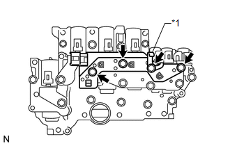
1. REMOVE TRANSMISSION WIRE
.gif)
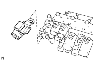
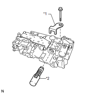
2. REMOVE ATF TEMPERATURE SENSOR ASSEMBLY
|
(a) Remove the 4 bolts, ATF temperature sensor assembly and clamp from the valve body assembly. Text in Illustration
|
|
|
(b) Remove the O-ring from the ATF temperature sensor assembly. Text in Illustration
|
|
.png)
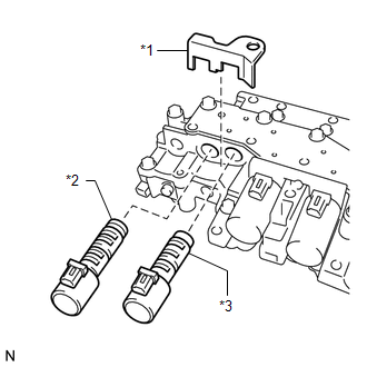
3. REMOVE SHIFT SOLENOID VALVE SL
|
(a) Remove the shift solenoid valve SL from the valve body assembly. |
|
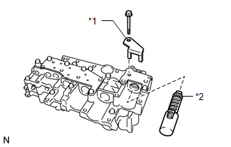
4. REMOVE SHIFT SOLENOID VALVE SLT
|
(a) Remove the lock plate and shift solenoid valve SLT from the valve body assembly. Text in Illustration
|
|
5. REMOVE SHIFT SOLENOID VALVE SLU
(a) Remove the shift solenoid valve SLU from the valve body assembly.
6. REMOVE SHIFT SOLENOID VALVE SL2
|
(a) Remove the bolt, lock plate and shift solenoid valve SL2 from the valve body assembly. Text in Illustration
|
|
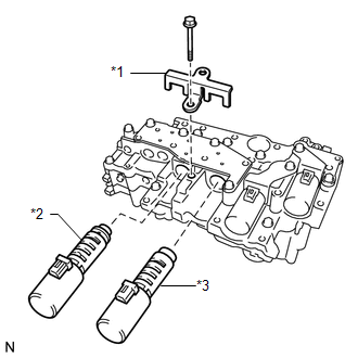
7. REMOVE SHIFT SOLENOID VALVE SL1
(a) Remove the shift solenoid valve SL1 from the valve body assembly.
8. REMOVE SHIFT SOLENOID VALVE SL3
|
(a) Remove the bolt, lock plate and shift solenoid valve SL3 from the valve body assembly. Text in Illustration
|
|
9. REMOVE SHIFT SOLENOID VALVE SL4
|
(a) Remove the bolt, lock plate and shift solenoid valve SL4 from the valve body assembly. Text in Illustration
|
|
 Components
COMPONENTS
ILLUSTRATION
ILLUSTRATION
...
 Removal
REMOVAL
PROCEDURE
1. REMOVE AUTOMATIC TRANSAXLE ASSEMBLY
HINT:
See the steps from "Remove Engine Assembly with transaxle" through "Remove Automatic
Transaxle Assembly" (See p ...
Other materials about Toyota Venza:
Transponder Key Amplifier
Components
COMPONENTS
ILLUSTRATION
Removal
REMOVAL
PROCEDURE
1. REMOVE FRONT DOOR SCUFF PLATE
2. REMOVE COWL SIDE TRIM SUB-ASSEMBLY
3. REMOVE LOWER NO. 1 INSTRUMENT PANEL FINISH PANEL
4. REMOVE LOWER STEERING COLUMN COVER
5. REMOVE ...
Purge Valve
Components
COMPONENTS
ILLUSTRATION
Inspection
INSPECTION
PROCEDURE
1. INSPECT NO. 1 VACUUM SWITCHING VALVE ASSEMBLY
(a) Measure the resistance according to the value(s) in the table below.
Standard Resistance:
Te ...
Tongue Plate Stopper
Components
COMPONENTS
ILLUSTRATION
Replacement
REPLACEMENT
PROCEDURE
1. REMOVE TONGUE PLATE STOPPER
(a) Slide the tongue plate above the installation position of the tongue
plate stopper, and temporarily hold it with adhesive tape.
...

0.1529