Toyota Venza: Disassembly
DISASSEMBLY
PROCEDURE
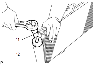
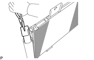
1. REMOVE COOLER DRYER
|
(a) Using a 14 mm straight hexagon wrench, remove the cap from the modulator. Text in Illustration
|
|
|
(b) Using pliers, remove the cooler dryer. |
|
 Removal
REMOVAL
PROCEDURE
1. DISCONNECT CABLE FROM NEGATIVE BATTERY TERMINAL
NOTICE:
When disconnecting the cable, some systems need to be initialized after the cable
is reconnected (See page ).
2. RE ...
 Installation
INSTALLATION
PROCEDURE
1. INSTALL COOLER CONDENSER ASSEMBLY
(a) Install the cooler condenser assembly with the 4 bolts.
Torque:
6.0 N·m {61 kgf·cm, 53 in·lbf}
HINT:
If th ...
Other materials about Toyota Venza:
System Description
SYSTEM DESCRIPTION
1. GENERAL
The windshield deicer system's thin heater wires are attached to the inside of
the front window and deice the window surface quickly. The indicator light illuminates
while the system is operating. The system automaticall ...
Transfer Case Front Oil Seal(for Rh Side)
Components
COMPONENTS
ILLUSTRATION
Replacement
REPLACEMENT
PROCEDURE
1. DRAIN TRANSFER OIL
(a) Remove the transfer drain plug and gasket to drain the transfer oil.
(b) Install a new gasket and the transfer drain plug.
Torque:
49 N·m {500 kgf ...
Daytime Running Light Relay Circuit
DESCRIPTION
The main body ECU (driver side junction block assembly) controls the daytime
running lights.
WIRING DIAGRAM
1. for Halogen Headlight
2. for HID Headlight
PROCEDURE
1.
PERFORM ACTIVE TEST USING TECHSTREAM
...

0.1298