Toyota Venza: Components
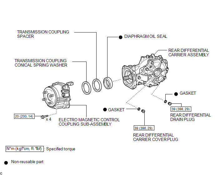
COMPONENTS
ILLUSTRATION
.png)
ILLUSTRATION

 Replacement
REPLACEMENT
PROCEDURE
1. REMOVE CENTER EXHAUST PIPE ASSEMBLY
(a) Remove the center exhaust pipe assembly.
HINT:
Refer to the instructions for Removal of the exhaust pipe (See page
for 2GR-FE, ...
Other materials about Toyota Venza:
Installation
INSTALLATION
PROCEDURE
1. TEMPORARILY INSTALL REAR NO. 1 SUSPENSION ARM ASSEMBLY LH
(a) Temporarily install the rear No. 1 suspension arm assembly LH to
the rear suspension member with the bolt (B).
Text in Illustration
...
Camshaft Position "B" - Timing Over-Advanced or System Performance (Bank 1)
(P0014,P0015)
DESCRIPTION
Refer to DTC P0013 (See page ).
DTC No.
DTC Detection Condition
Trouble Area
P0014
The valve timing is stuck at a certain value when in the advance range
(2 trip detection logic).
...
Crankshaft Position Sensor
Components
COMPONENTS
ILLUSTRATION
Removal
REMOVAL
PROCEDURE
1. REMOVE FRONT FENDER APRON SEAL RH
2. REMOVE CRANKSHAFT POSITION SENSOR
(a) Disconnect the sensor connector.
(b) Remove the bolt and sensor.
Inspection
INSPECTION
PROCEDURE ...

0.1588