
Toyota Venza: Components
COMPONENTS
ILLUSTRATION
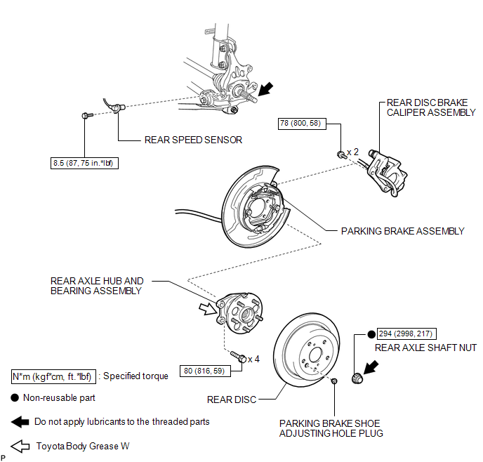

 On-vehicle Inspection
ON-VEHICLE INSPECTION
CAUTION / NOTICE / HINT
HINT:
Use the same procedure for the RH side and LH side.
The procedure listed below is for the LH side.
PROCEDURE
1. REMOVE REAR W ...
Other materials about Toyota Venza:
Removal
REMOVAL
CAUTION / NOTICE / HINT
HINT:
Use the same procedure for the LH side and RH side.
The following procedure is for the LH side.
PROCEDURE
1. REMOVE ENGINE ASSEMBLY WITH TRANSAXLE (for 2GR-FE)
HINT:
Refer to the procedure up to Re ...
Dtc Check / Clear
DTC CHECK / CLEAR
1. CHECK DTC
(a) Connect the Techstream to the DLC3.
(b) Turn the ignition switch to ON.
(c) Turn the Techstream on.
(d) Enter the following menus: Body Electrical / Back Door / DTC.
HINT:
Refer to the Techstream operator's manual ...
Front Crankshaft Oil Seal
Components
COMPONENTS
ILLUSTRATION
Removal
REMOVAL
PROCEDURE
1. REMOVE FRONT WHEEL RH
2. REMOVE NO. 1 ENGINE UNDER COVER
3. SEPARATE FRONT FENDER LINER RH
4. REMOVE FRONT FENDER APRON SEAL RH
5. REMOVE V-RIBBED BELT
6. REMOVE CRANKSHAFT ...

0.1189