Toyota Venza: Components
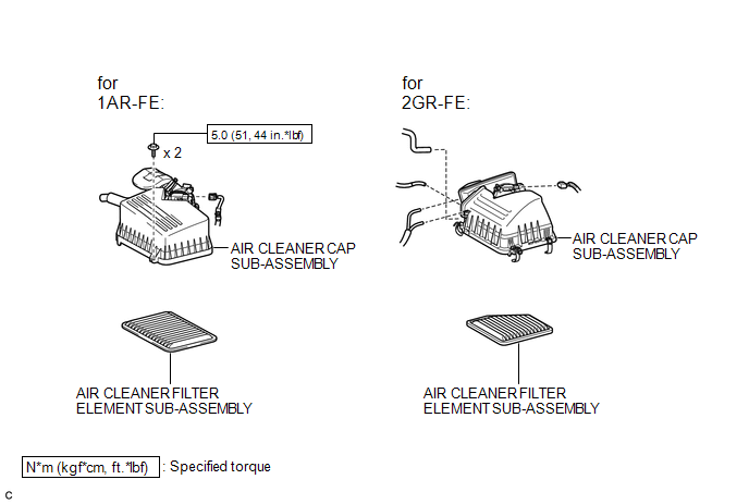
COMPONENTS
ILLUSTRATION
ILLUSTRATION
.png)
ILLUSTRATION

 Disassembly
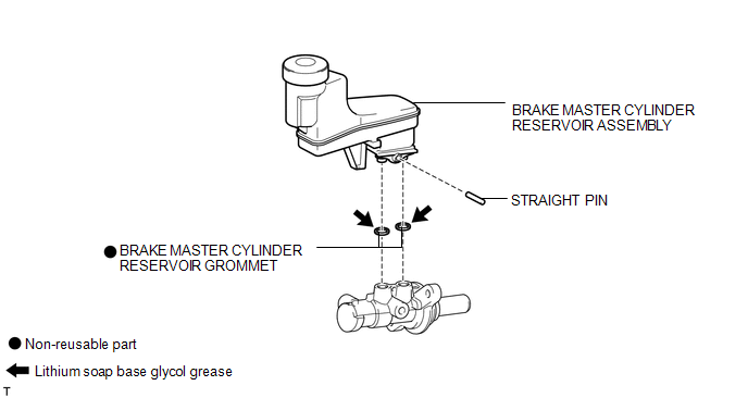
DISASSEMBLY
PROCEDURE
1. REMOVE BRAKE MASTER CYLINDER RESERVOIR ASSEMBLY
(a) Mount the brake master cylinder sub-assembly in a vise.
NOTICE:
Place aluminum plates on the vise to prevent damage to ...
Other materials about Toyota Venza:
Removal
REMOVAL
PROCEDURE
1. REMOVE UPPER CONSOLE PANEL SUB-ASSEMBLY (w/o Seat Heater System)
2. REMOVE UPPER CONSOLE PANEL SUB-ASSEMBLY (w/ Seat Heater System)
3. REMOVE NO. 2 CONSOLE BOX CARPET
4. REMOVE CONSOLE BOX ASSEMBLY
5. REMOVE AIR CONDITION ...
Back Door Entry Lock and Unlock Functions do not Operate
DESCRIPTION
When the back door entry lock and unlock functions do not operate, one of the
following may be malfunctioning: 1) power door lock control system; 2) outside electrical
key oscillator (for rear side); 3) certification ECU (smart key ECU assembl ...
On-vehicle Inspection
ON-VEHICLE INSPECTION
PROCEDURE
1. CHECK BATTERY CONDITION
NOTICE:
If the battery is weak or if the engine is difficult to start, perform the following
procedure.
(a) Check the battery for damage and deformation. If severe damage, deformation
or leaka ...

0.1451