Toyota Venza: Components
COMPONENTS
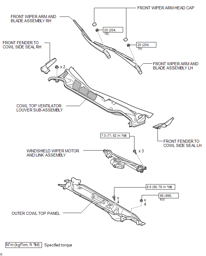
ILLUSTRATION
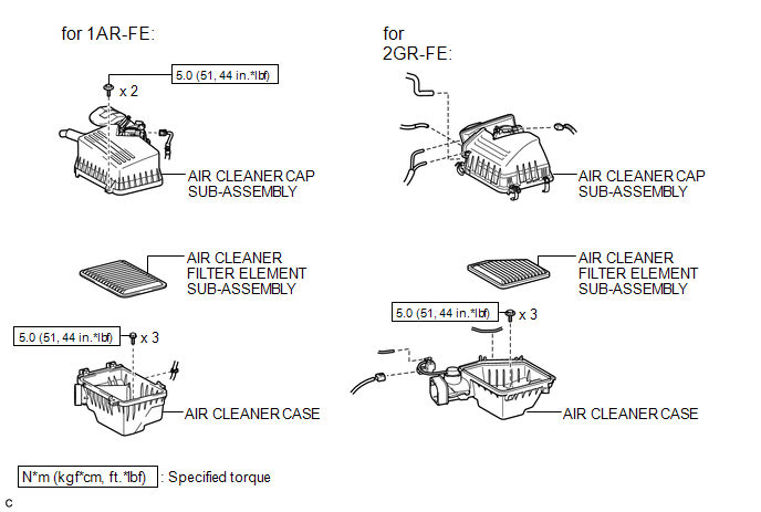
ILLUSTRATION
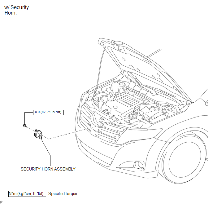
ILLUSTRATION
ILLUSTRATION

ILLUSTRATION
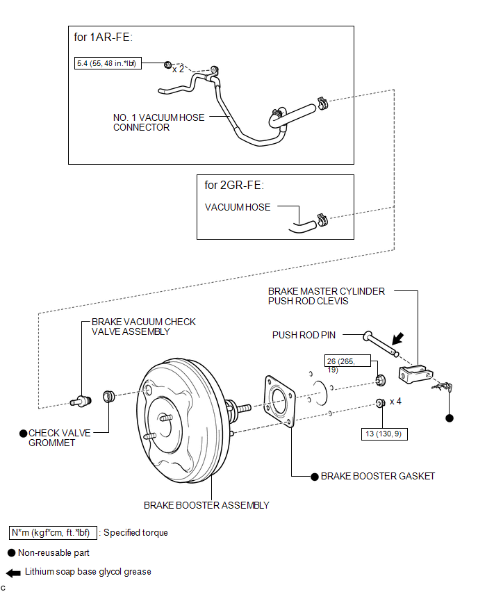
 Brake Booster
...
 On-vehicle Inspection
ON-VEHICLE INSPECTION
PROCEDURE
1. INSPECT BRAKE BOOSTER ASSEMBLY
(a) Airtightness check
(1) Start the engine and stop it after 1 or 2 minutes. Slowly depress
the brake pedal seve ...
Other materials about Toyota Venza:
Differential System
Precaution
PRECAUTION
Before disassembly, clean the outside of the differential assembly and
remove any sand or mud to prevent it from entering the inside of the assembly
during disassembly and installation.
When removing an installed pa ...
On-vehicle Inspection
ON-VEHICLE INSPECTION
PROCEDURE
1. CHECK THROTTLE BODY ASSEMBLY
(a) Check the throttle control motor operating sounds.
(1) Turn the ignition switch to ON.
(2) When pressing the accelerator pedal, check the operating sound of the running
motor. Make sure ...
Data List / Active Test
DATA LIST / ACTIVE TEST
HINT:
Using the Techstream to read the Data List allows the values or states of switches,
sensors, actuators and other items to be read without removing any parts. This non-intrusive
inspection can be very useful because intermitt ...

0.1152