Toyota Venza: Components
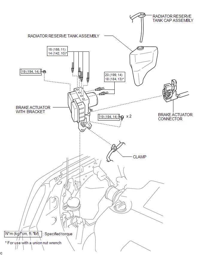
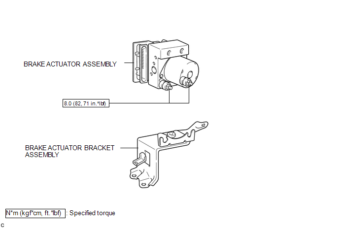
COMPONENTS
ILLUSTRATION
ILLUSTRATION
 Brake Actuator
...
 On-vehicle Inspection
ON-VEHICLE INSPECTION
PROCEDURE
1. CONNECT TECHSTREAM
(a) Connect the Techstream to the DLC3.
(b) Start the engine and run it at idle.
(c) Enter the following menus: Chassis / ABS/VSC/TRAC / Acti ...
Other materials about Toyota Venza:
Mechanical System Tests
MECHANICAL SYSTEM TESTS
1. STALL SPEED TEST
HINT:
This test is to check the overall performance of the engine and transaxle.
CAUTION:
Driving test should be done on a paved surface (a surface that is not
slippery).
To ensure safety, perfor ...
Air Fuel Ratio Sensor
Components
COMPONENTS
ILLUSTRATION
Removal
REMOVAL
PROCEDURE
1. REMOVE NO. 1 ENGINE COVER SUB-ASSEMBLY
2. REMOVE COOL AIR INTAKE DUCT SEAL
3. REMOVE INLET AIR CLEANER ASSEMBLY
4. REMOVE NO. 1 EXHAUST MANIFOLD HEAT INSULATOR
5. REMOV ...
Initialization
INITIALIZATION
1. RESET BACK DOOR CLOSE POSITION (w/ POWER BACK DOOR SYSTEM)
NOTICE:
Perform initialization of the power back door system (power back door ECU initialization)
if one of the following is performed:
The cable is disconnected from the ...

0.1141