Toyota Venza: Components
COMPONENTS
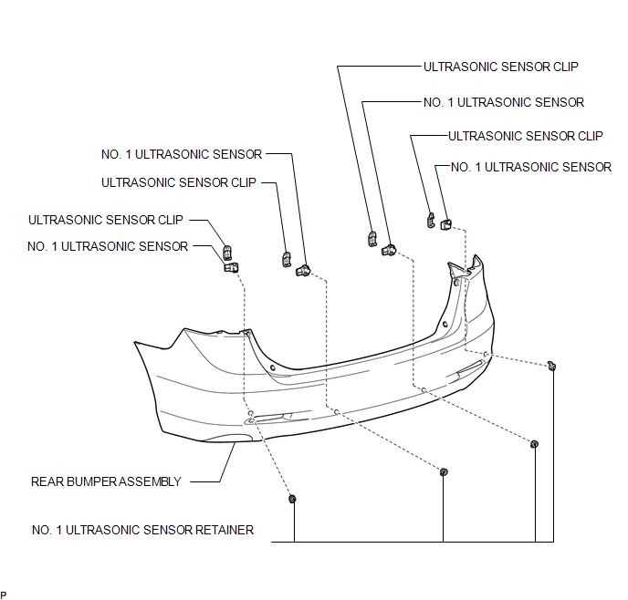
ILLUSTRATION

 Inspection
INSPECTION
PROCEDURE
1. INSPECT NO. 1 ULTRASONIC SENSOR
(a) Measure the resistance according to the value(s) in the table below.
Standard Resistance:
Tester Conne ...
Other materials about Toyota Venza:
Ignition Switch
Components
COMPONENTS
ILLUSTRATION
Removal
REMOVAL
PROCEDURE
1. REMOVE LOWER STEERING COLUMN COVER
2. REMOVE UPPER STEERING COLUMN COVER
3. REMOVE IGNITION SWITCH
(a) Remove the 2 screws and ignition switch.
...
System Description
SYSTEM DESCRIPTION
1. SYSTEM DESCRIPTION
(a) The Electronic Controlled Automatic Transaxle (ECT) is an automatic transaxle
that has its shift timing electronically controlled by the Transmission Control
Module (TCM). The TCM detects electrical signals th ...
Open in CAN Main Bus Line
DESCRIPTION
There may be an open circuit in the CAN bus main wire and/or the DLC3 branch
wire when the resistance between terminals 6 (CANH) and 14 (CANL) of the DLC3 is
70 Ω or higher.
Symptom
Trouble Area
Resista ...

0.1464