Toyota Venza: Components
COMPONENTS
ILLUSTRATION
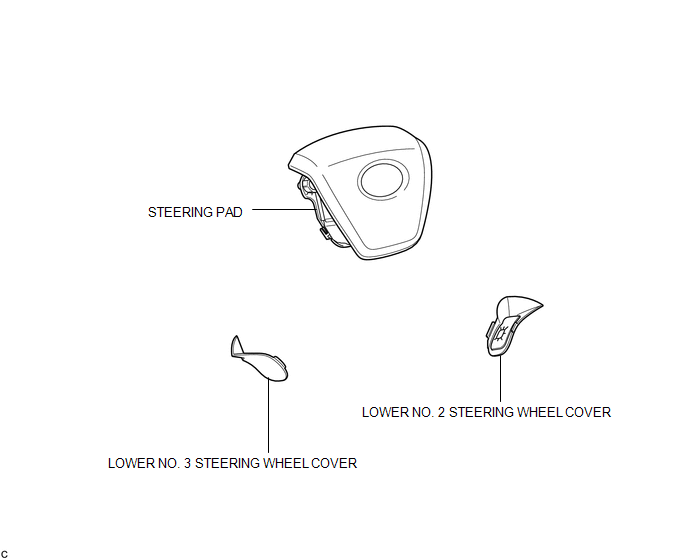
 Steering Pad
...
 On-vehicle Inspection
ON-VEHICLE INSPECTION
CAUTION / NOTICE / HINT
CAUTION:
Be sure to follow the correct removal and installation procedures of the steering
pad.
PROCEDURE
1. INSPECT STEERING PAD (Vehicle not Invo ...
Other materials about Toyota Venza:
No Sound can be Heard from Speakers
PROCEDURE
1.
CHECK AUDIO SETTINGS
(a) In sound setting mode, set volume, fader and balance to the initial values
and check that the sound is normal.
OK:
Audio system returns to normal.
HINT:
Sound quality adjustment mea ...
Key battery
Replace the battery with a new one if it is discharged.
- You will need the following items:
• Flathead screwdriver (To prevent damage to the key, cover the tip of the screwdriver
with rag.)
• Small Phillips-head screwdriver
• Lithium battery ...
Components
COMPONENTS
ILLUSTRATION
ILLUSTRATION
ILLUSTRATION
ILLUSTRATION
ILLUSTRATION
ILLUSTRATION
ILLUSTRATION
ILLUSTRATION
ILLUSTRATION
ILLUSTRATION
ILLUSTRATION
ILLUSTRATION
...

0.1609