Toyota Venza: Components
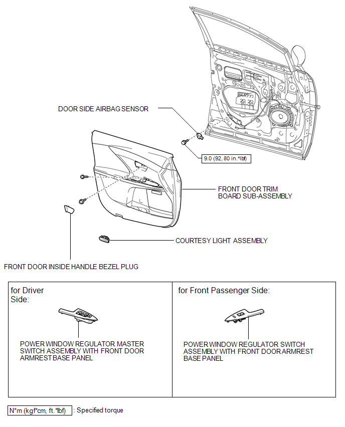
COMPONENTS
ILLUSTRATION

 On-vehicle Inspection
ON-VEHICLE INSPECTION
CAUTION / NOTICE / HINT
CAUTION:
Be sure to follow the correct removal and installation procedures of the door
side airbag sensor.
PROCEDURE
1. INSPECT DOOR SIDE AIRBAG SE ...
Other materials about Toyota Venza:
Height Control Sensor Data Out of Range When Initializing (B2452)
DESCRIPTION
The headlight leveling ECU assembly stores this DTC if the sensor value received
from the height control sensor is out of range when performing initialization of
the headlight leveling ECU assembly; for example, the vehicle is not level or bei ...
ABS Warning Light does not Come ON
DESCRIPTION
The skid control ECU is connected to the combination meter via CAN communication.
WIRING DIAGRAM
Refer to ABS Warning Light Remains ON (See page
).
PROCEDURE
1.
CHECK CAN COMMUNICATION SYSTEM
(a) Check if a C ...
Rear Power Window RH does not Operate with Rear Power Window Switch RH
DESCRIPTION
When the engine is running or the ignition switch is ON, the power window regulator
motor assembly (for rear RH side) is operated by the power window regulator switch
assembly (for rear RH side). The power window regulator motor assembly (for ...

0.1498