
Toyota Venza: Components
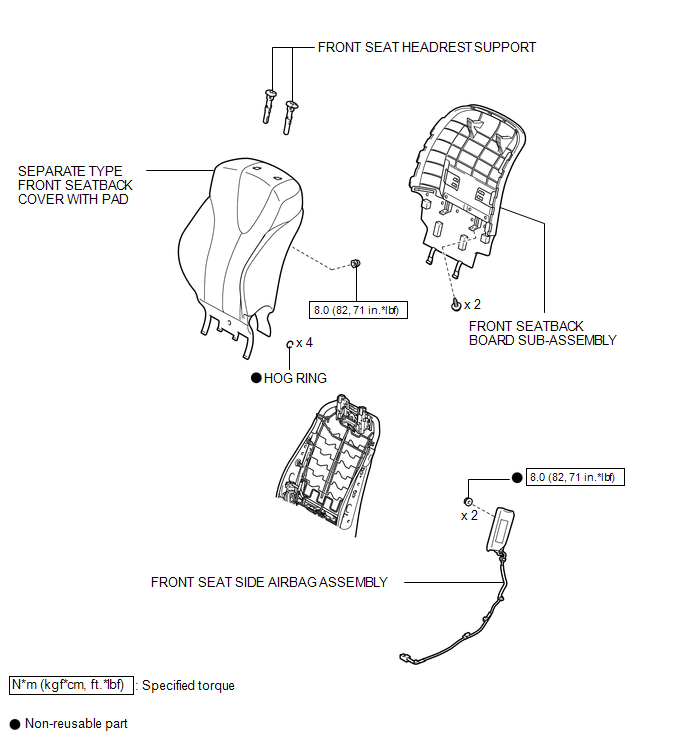
COMPONENTS
ILLUSTRATION

 On-vehicle Inspection
ON-VEHICLE INSPECTION
CAUTION / NOTICE / HINT
CAUTION:
Be sure to follow the correct removal and installation procedures of the front
seat side airbag assembly.
PROCEDURE
1. INSPECT FRONT SEAT ...
Other materials about Toyota Venza:
Precaution
PRECAUTION
1. PRECAUTION FOR DISCONNECTING CABLE FROM NEGATIVE BATTERY TERMINAL
NOTICE:
When disconnecting the cable from the negative (-) battery terminal, initialize
the following systems after the terminal is reconnected.
System Name
...
Disassembly
DISASSEMBLY
PROCEDURE
1. INSPECT FRONT OIL PUMP AND GEAR BODY SUB-ASSEMBLY
2. REMOVE STATOR SHAFT ASSEMBLY
(a) Using a "TORX" wrench (T30), remove the 16 bolts and stator shaft
assembly from the oil pump body.
NOTICE:
Keep ...
Removal
REMOVAL
PROCEDURE
1. DISCONNECT CABLE FROM NEGATIVE BATTERY TERMINAL
CAUTION:
Wait at least 90 seconds after disconnecting the cable from the negative (-)
battery terminal to disable the SRS system.
NOTICE:
When disconnecting the cable, some systems ne ...

0.1596