Toyota Venza: Disassembly
DISASSEMBLY
PROCEDURE
1. REMOVE INTAKE VALVE
|
(a) Using SST and wooden blocks, compress the compression spring and remove the valve spring retainer locks. SST: 09202-70020 09202-00010 |
|
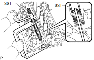
(b) Remove the retainer, compression spring and valve.
HINT:
Arrange the removed parts in the correct order.
2. REMOVE EXHAUST VALVE
|
(a) Using SST and wooden blocks, compress the compression spring and remove the valve spring retainer locks. SST: 09202-70020 09202-00010 |
|
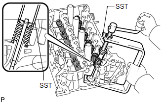
(b) Remove the retainer, compression spring and valve.
HINT:
Arrange the removed parts in the correct order.
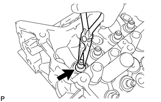
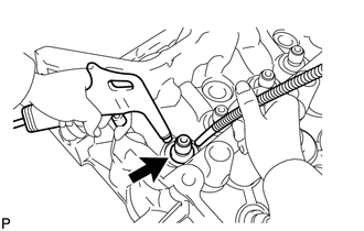
3. REMOVE VALVE STEM OIL SEAL
|
(a) Using needle-nose pliers, remove the oil seals. |
|
4. REMOVE VALVE SPRING SEAT
|
(a) Using compressed air and a Magnet Hand, remove the valve spring seat by blowing air onto it. |
|
5. REMOVE NO. 1 STRAIGHT SCREW PLUG
NOTICE:
If water leaks from the No. 1 screw plug or the plug is corroded, replace it.
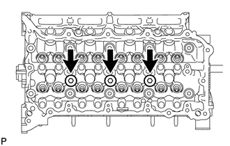
(a) Using a 10 mm hexagon wrench, remove the 3 screw plugs and 3 gaskets.
6. REMOVE NO. 2 STRAIGHT SCREW PLUG
NOTICE:
If water leaks from the No. 2 screw plug or the plug is corroded, replace it.
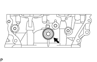
(a) Using a 14 mm hexagon wrench, remove the screw plug and gasket.
7. REMOVE STUD BOLT
NOTICE:
If a stud bolt is deformed or its threads are damaged, replace it.
 Components
COMPONENTS
ILLUSTRATION
...
 Inspection
INSPECTION
PROCEDURE
1. INSPECT CYLINDER HEAD SUB-ASSEMBLY
(a) Using a precision straightedge and feeler gauge, measure the warpage of the
contact surfaces where the cylinder head contacts the cy ...
Other materials about Toyota Venza:
Portable Player cannot be Connected Manually/Automatically
CAUTION / NOTICE / HINT
HINT:
Some versions of "Bluetooth" compatible audio players may not function properly,
or the functions may be limited using the navigation receiver assembly, even if
the portable audio player itself can play files (See ...
Reverse Shift-linked Function of Power Mirrors does not Operate
SYSTEM DESCRIPTION
On receiving a reverse signal from the park/neutral position switch assembly,
the ECM sends the reverse signal to the main body ECU (driver side junction block
assembly) via CAN communication. When receiving the reverse signal, the main ...
Installation
INSTALLATION
CAUTION / NOTICE / HINT
HINT:
Use the same procedure for the RH side and LH side.
The procedure listed below is for the LH side.
PROCEDURE
1. SECURE REAR SHOCK ABSORBER WITH COIL SPRING
2. INSTALL REAR LOWER COIL SPRING ...

0.1705