Toyota Venza: Components
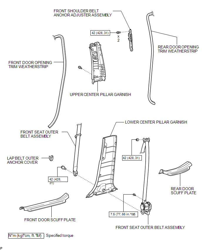
COMPONENTS
ILLUSTRATION

 Precaution
PRECAUTION
CAUTION:
Replace any faulty seat belt components (outer belt, inner belt, bolts, nuts,
adjustable shoulder anchor, tether anchor hardware and other related parts). When
inspecting a v ...
Other materials about Toyota Venza:
Removal
REMOVAL
PROCEDURE
1. DISCONNECT CABLE FROM NEGATIVE BATTERY TERMINAL
NOTICE:
When disconnecting the cable, some systems need to be initialized after the cable
is reconnected (See page ).
2. REMOVE UPPER CONSOLE PANEL SUB-ASSEMBLY (w/o Seat Heater Syste ...
System Description
SYSTEM DESCRIPTION
1. FUNCTION OF MAIN COMPONENTS
Component
Function
Accessory Meter Assembly
AWD Warning Light
Illuminates to warn the driver of a malfunction in the active
torque ...
Diagnostic Trouble Code Chart
DIAGNOSTIC TROUBLE CODE CHART
HINT:
If a trouble code is stored during the DTC check, inspect the trouble areas listed
for that code. For details of the code, refer to the "See page" below.
Certification ECU (Smart Key ECU Assembly)
...

0.1184