Toyota Venza: Components
COMPONENTS
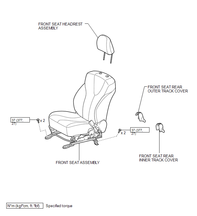
ILLUSTRATION
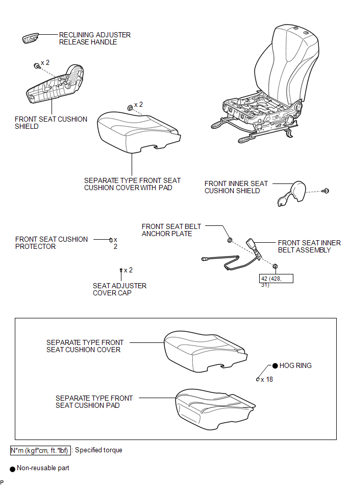
ILLUSTRATION
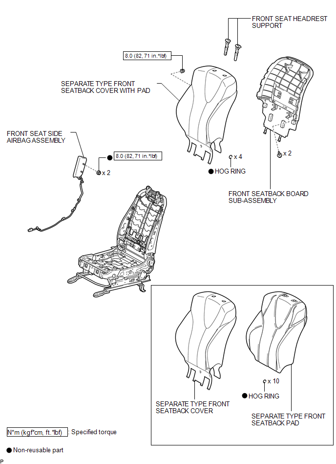
ILLUSTRATION
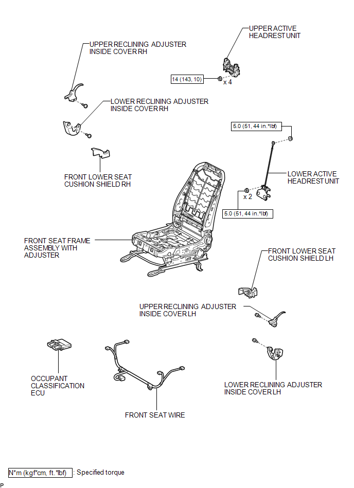
ILLUSTRATION

 Removal
REMOVAL
PROCEDURE
1. PRECAUTION
CAUTION:
Be sure to read Precaution thoroughly before servicing (See page
).
If the front seat side airbag assembly was deployed, replace the front ...
Other materials about Toyota Venza:
Freeze Frame Data
FREEZE FRAME DATA
1. DESCRIPTION
The ECM records vehicle and driving condition information as freeze
frame data the moment a DTC is stored. When troubleshooting, freeze frame
data can be helpful in determining whether the vehicle was moving or ...
Power Back Door cannot be Opened or Closed Using the Power Back Door Switch
DESCRIPTION
When the power back door cannot be opened or closed using the power back door
control switch, one of the following may be malfunctioning: 1) power back door control
switch circuit, 2) power back door ECU (power back door motor unit) or 3) main ...
Precaution
PRECAUTION
NOTICE:
When disconnecting the cable from the negative (-) battery terminal, initialize
the following systems after the cable is reconnected.
System Name
See Procedure
Back Door Closer System
...

0.1761