Toyota Venza: Removal
REMOVAL
PROCEDURE
1. PRECAUTION
CAUTION:
- Be sure to read Precaution thoroughly before servicing (See page
.gif) ).
). - If the front seat side airbag assembly was deployed, replace the front seat side airbag assembly, front seat frame assembly with adjuster, separate type front seatback cover and separate type front seatback pad with the necessary parts in accordance with the extent of the collision damage.
2. DISCONNECT CABLE FROM NEGATIVE BATTERY TERMINAL
CAUTION:
Wait at least 90 seconds after disconnecting the cable from the negative (-) battery terminal to disable the SRS system
NOTICE:
When disconnecting the cable, some systems need to be initialized after the cable
is reconnected (See page ).
3. REMOVE FRONT SEAT HEADREST ASSEMBLY
4. REMOVE FRONT SEAT REAR OUTER TRACK COVER
(a) Lift up the seat track adjusting handle and move the front seat assembly to the foremost position.
|
(b) Disengage the 2 claws and remove the front seat rear outer track cover. |
|
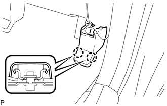
5. REMOVE FRONT SEAT REAR INNER TRACK COVER
|
(a) Disengage the 2 claws and remove the front seat rear inner track cover. |
|

6. REMOVE FRONT SEAT ASSEMBLY
|
(a) Remove the 2 bolts on rear side of the front seat assembly. |
|
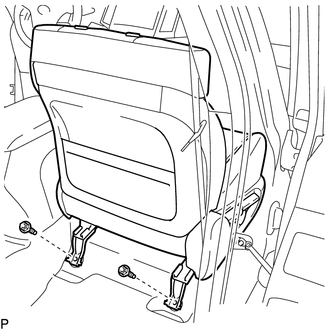
(b) Lift up the seat track adjusting handle and move the front seat assembly to the rearmost position.
|
(c) Remove the 2 bolts on front side of the front seat assembly. |
|
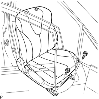
(d) Lift up the seat track adjusting handle and move the front seat assembly to the center position. Also, operate the reclining adjuster release handle and move the front seatback assembly to the upright position.
(e) Disconnect each connector under the front seat assembly.
(f) Remove the front seat assembly.
NOTICE:
Be careful not to damage the vehicle body.
 Components
COMPONENTS
ILLUSTRATION
ILLUSTRATION
ILLUSTRATION
ILLUSTRATION
...
 Reassembly
REASSEMBLY
PROCEDURE
1. INSTALL FRONT SEAT WIRE
(a) Engage the 2 clamps to install the front seat wire.
(b) Connect the 4 connectors.
2. ...
Other materials about Toyota Venza:
Replacement
REPLACEMENT
PROCEDURE
1. RECOVER REFRIGERANT FROM REFRIGERATION SYSTEM
(a) Start up the engine.
(b) Turn the A/C switch on.
(c) Operate the cooler compressor at an engine speed of approximately 1000 rpm
for 5 to 6 minutes to circulate the refrigerant. T ...
Vehicle Speed or Engine Speed Signal Malfunction (C2173/73)
DESCRIPTION
The tire pressure warning ECU receives a vehicle speed signal from the combination
meter and an engine speed signal from the ECM. The tire pressure warning ECU uses
these signals to detect DTCs C2121/21 to C2124/24 (No Signal from Transmitter) ...
Removal
REMOVAL
CAUTION / NOTICE / HINT
CAUTION:
Some of these service operations affect the SRS airbag system. Read the precautionary
notices concerning the SRS airbag system before servicing (See page
).
NOTICE:
Be sure to read "Precaution" thorou ...

0.15