Toyota Venza: Components
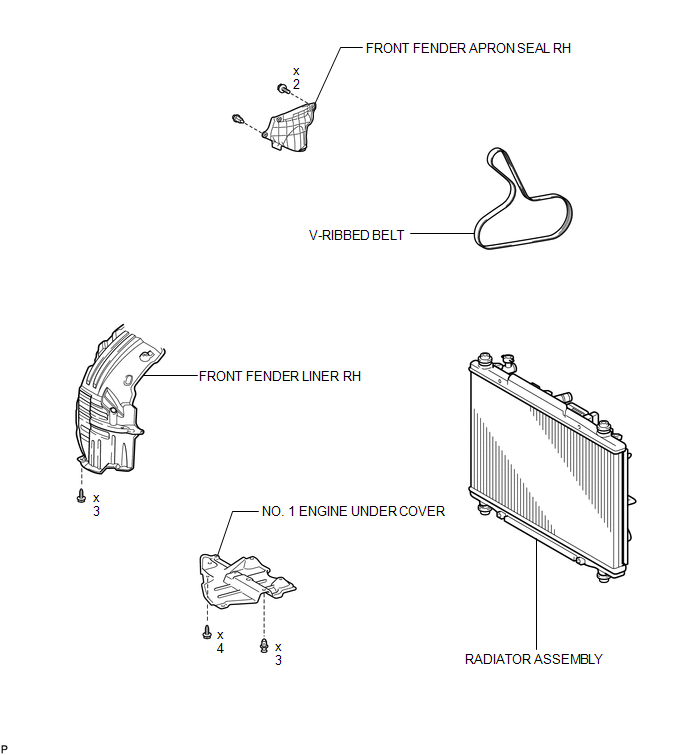
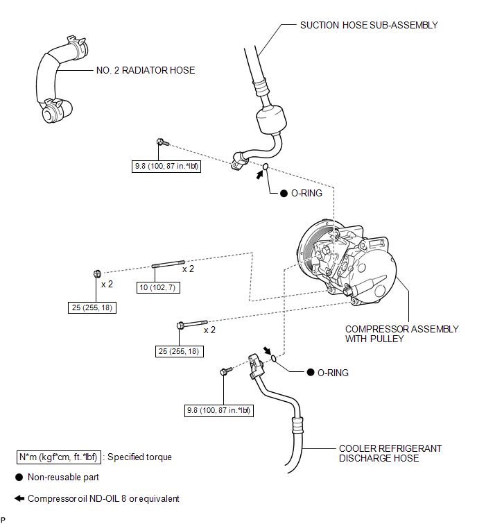
COMPONENTS
ILLUSTRATION
ILLUSTRATION

 On-vehicle Inspection
ON-VEHICLE INSPECTION
PROCEDURE
1. INSPECT COMPRESSOR FOR METALLIC SOUND
(a) Check if there is abnormal metallic sound from the A/C compressor (compressor
with pulley) when the A/C switch is on a ...
Other materials about Toyota Venza:
TC and CG Terminal Circuit
DESCRIPTION
Connecting terminals TC and CG of the DLC3 causes the AWD control ECU to display
2-digit DTCs by flashing the AWD warning light.
HINT:
When each warning light remains blinking, a short to ground in the wiring of
terminal TC of the DLC3 or an ...
Installation
INSTALLATION
CAUTION / NOTICE / HINT
HINT:
Use the same procedure for the RH side and LH side.
The procedure listed below is for the LH side.
PROCEDURE
1. INSTALL FRONT POWER WINDOW REGULATOR MOTOR ASSEMBLY
NOTICE:
The regulator arm mu ...
ECU Power Source Circuit
DESCRIPTION
This circuit provides power to operate the transponder key ECU assembly.
WIRING DIAGRAM
CAUTION / NOTICE / HINT
NOTICE:
If the transponder key ECU assembly is replaced, register the key and ECU communication
ID (See page ).
PROCEDURE
...

0.1327