Toyota Venza: Components
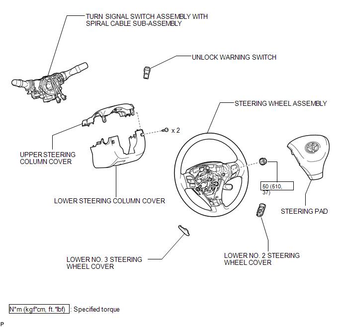
COMPONENTS
ILLUSTRATION

 Inspection
INSPECTION
PROCEDURE
1. INSPECT UNLOCK WARNING SWITCH ASSEMBLY
(a) Measure the resistance according to the value(s) in the table below.
Standard Resistance:
Tester Connection
...
Other materials about Toyota Venza:
Removal
REMOVAL
PROCEDURE
1. REMOVE COOL AIR INTAKE DUCT SEAL
(a) Using a clip remover, remove the 12 clips and cool air intake duct
seal.
2. REMOVE RADIATOR GRILLE
3. REMOVE FRONT BUMPER ASSEMBLY
...
Installation
INSTALLATION
PROCEDURE
1. INSTALL YAW RATE AND ACCELERATION SENSOR
(a) Install the yaw rate and acceleration sensor to the bracket with
the 2 nuts.
Torque:
5.0 N·m {51 kgf·cm, 44 in·lbf}
...
All Doors LOCK/UNLOCK Functions do not Operate Via Door Control Switch
DESCRIPTION
The main body ECU (driver side junction block assembly) receives switch signals
from the door control switch and activates the door lock motor on each door according
to these signals.
WIRING DIAGRAM
PROCEDURE
1.
REA ...

0.1526