Toyota Venza: Components
COMPONENTS
ILLUSTRATION
.png)
ILLUSTRATION
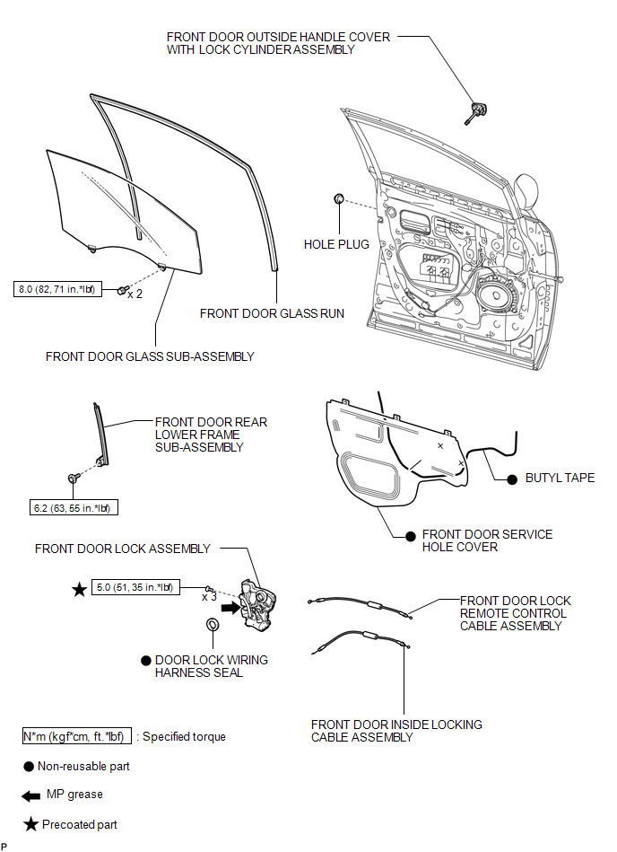
 Front Door Lock
...
 Removal
REMOVAL
PROCEDURE
1. DISCONNECT CABLE FROM NEGATIVE BATTERY TERMINAL
CAUTION:
Wait at least 90 seconds after disconnecting the cable from the negative (-)
battery terminal to disable the SRS sys ...
Other materials about Toyota Venza:
Data List / Active Test
DATA LIST / ACTIVE TEST
1. DATA LIST
HINT:
Using the Techstream to read the Data List allows the values or states of switches,
sensors, actuator and other items to be read without removing any parts. This non-intrusive
inspection can be very useful beca ...
Operation Check
OPERATION CHECK
1. MALFUNCTION BUZZER
(a) Open circuit or frozen
(1) If an open circuit is detected between the ultrasonic sensors and the clearance
warning ECU assembly, if a sensor malfunction is detected or if a sensor is covered
with foreign matter, ...
Components
COMPONENTS
ILLUSTRATION
ILLUSTRATION
ILLUSTRATION
ILLUSTRATION
ILLUSTRATION
...
© 2016-2026 Copyright www.tovenza.com

0.1468
0.1468