
Toyota Venza: Components
COMPONENTS
ILLUSTRATION
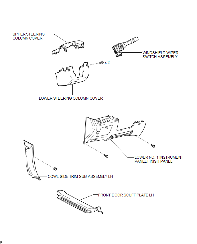
 Wiper Switch
...
 Removal
REMOVAL
PROCEDURE
1. REMOVE FRONT DOOR SCUFF PLATE LH
2. REMOVE COWL SIDE TRIM SUB-ASSEMBLY LH
3. REMOVE LOWER NO. 1 INSTRUMENT PANEL FINISH PANEL
4. REMOVE LOWER STEERING COLUMN COVER
...
Other materials about Toyota Venza:
Operation Check
OPERATION CHECK
1. CHECK BASIC FUNCTIONS
(a) When the back door is partially closed, check that the motor operates to
fully close (lock) the back door.
(b) Check that the back door can be opened.
(c) When the back door is partially closed and then the mo ...
Center Airbag Sensor Assembly Malfunction (B1000/31)
DESCRIPTION
The center airbag sensor assembly consists of a deceleration sensor, safing sensor,
drive circuit, diagnosis circuit, ignition control, etc.
If the center airbag sensor assembly receives signals from the deceleration sensor,
it determines whe ...
Data List / Active Test
DATA LIST / ACTIVE TEST
1. DATA LIST
HINT:
Using the Techstream to read the Data List allows the values or states of switches,
sensors, actuators and other items to be read without removing any parts. This non-intrusive
inspection can be very useful bec ...

0.1135