Toyota Venza: Components
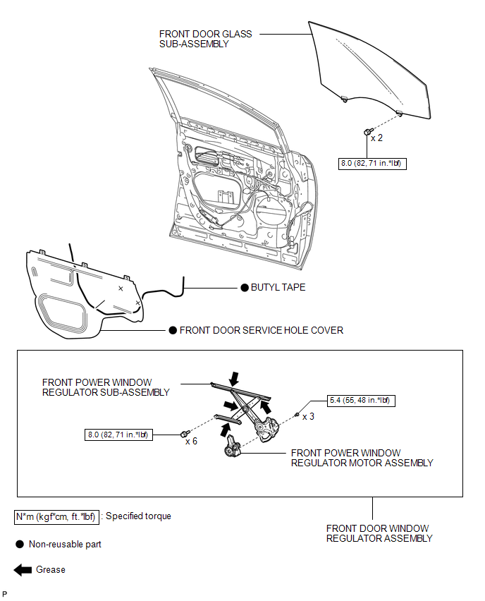
COMPONENTS
ILLUSTRATION
.png)
ILLUSTRATION

 Removal
REMOVAL
CAUTION / NOTICE / HINT
HINT:
Use the same procedure for the RH side and LH side.
The procedure listed below is for the LH side.
PROCEDURE
1. DISCONNECT CABLE FROM NEGAT ...
Other materials about Toyota Venza:
XM Tuner Antenna Disconnected (B15FE,B15FF)
DESCRIPTION
These DTCs are stored when a malfunction occurs in the roof antenna assembly
which is connected to the stereo component tuner assembly.
DTC No.
DTC Detection Condition
Trouble Area
B15FE
...
Height Control Sensor Data Out of Range When Initializing (B2452)
DESCRIPTION
The headlight leveling ECU assembly stores this DTC if the sensor value received
from the height control sensor is out of range when performing initialization of
the headlight leveling ECU assembly; for example, the vehicle is not level or bei ...
Diagnostic Trouble Code Chart
DIAGNOSTIC TROUBLE CODE CHART
HINT:
If a trouble code is displayed during the DTC check, inspect the circuit listed
for that code. For details of each code, refer to the relevant page listed under
respective "DTC Code" in the DTC chart.
Tire P ...

0.1695