Toyota Venza: Components
COMPONENTS
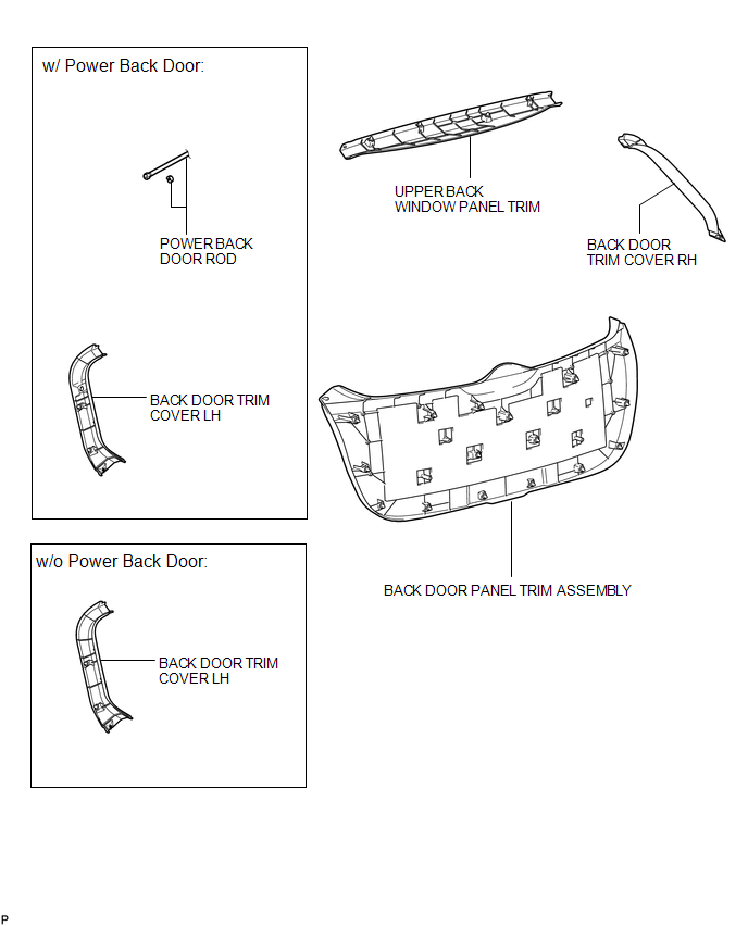
ILLUSTRATION
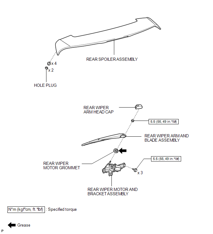
ILLUSTRATION
ILLUSTRATION
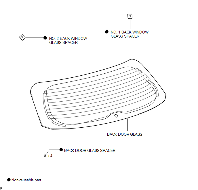
 Back Door Glass
...
 Installation
INSTALLATION
PROCEDURE
1. INSTALL NO. 2 BACK WINDOW GLASS SPACER
(a) Apply Primer G to the installation part of the No. 2 back window glass spacer.
HINT:
If primer is applied to an area that is n ...
Other materials about Toyota Venza:
System Description
SYSTEM DESCRIPTION
1. ACCESSORY METER ASSEMBLY
(a) Warning or Indicator
Item
Detail
Front passenger side seat belt warning light
Receives a front passenger side seat belt warning light signal from the
co ...
Diagnosis System
DIAGNOSIS SYSTEM
1. CHECK DLC3
(a) Check the DLC3 (See page ).
2. FUNCTION OF SRS WARNING LIGHT
(a) Primary check
(1) Turn the ignition switch off. Wait for at least 2 seconds, then turn the
ignition switch to ON. The SRS warning light comes on for app ...
Inspection
INSPECTION
PROCEDURE
1. INSPECT CYLINDER HEAD SUB-ASSEMBLY
(a) Using a precision straightedge and feeler gauge, measure the warpage of the
contact surfaces where the cylinder head contacts the cylinder block and manifold.
Maximum Warpage:
...

0.1326