Toyota Venza: Components
COMPONENTS
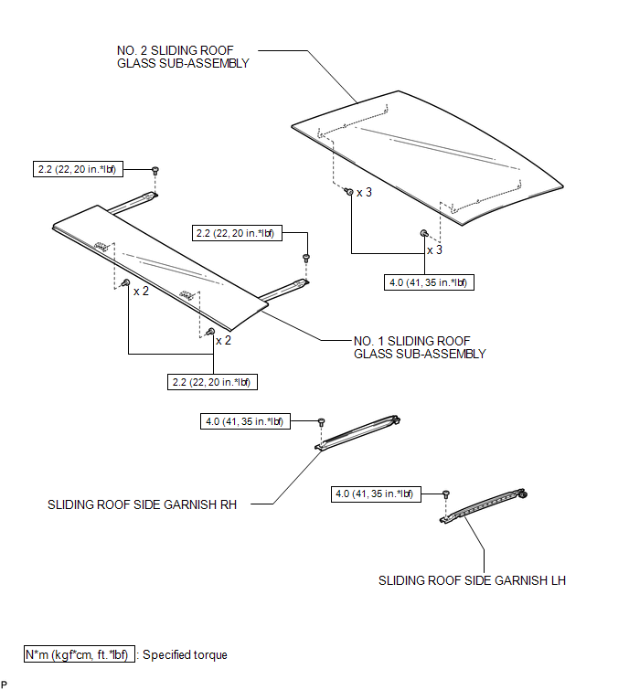
ILLUSTRATION
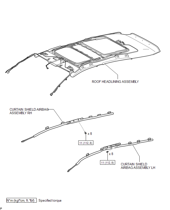
ILLUSTRATION
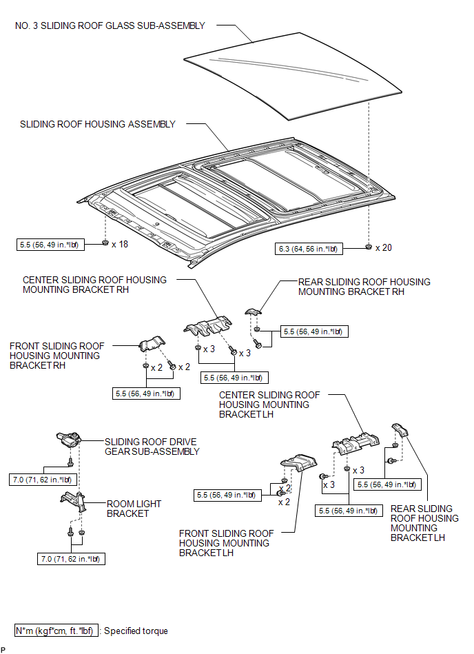
ILLUSTRATION
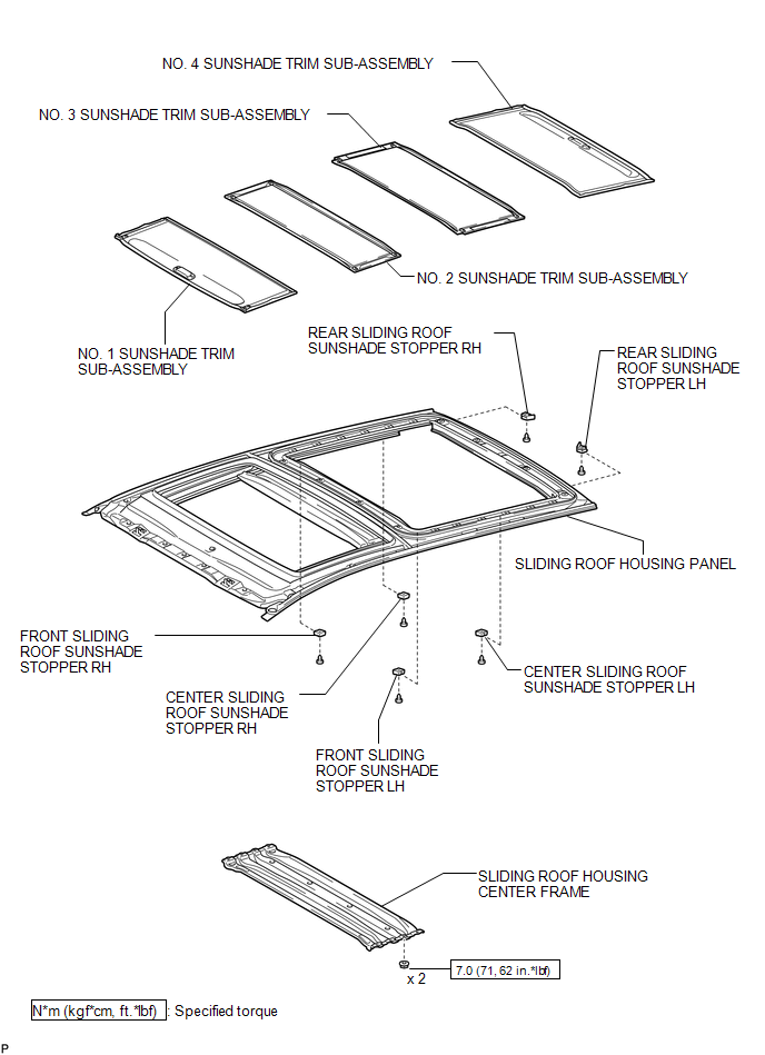
ILLUSTRATION

 Removal
REMOVAL
PROCEDURE
1. REMOVE NO. 1 SLIDING ROOF GLASS SUB-ASSEMBLY
(a) Fully open the No. 2 sliding roof glass sub-assembly.
(b) Using a T20 "TORX" socket wrench, remove the 6 ...
Other materials about Toyota Venza:
System Diagram
SYSTEM DIAGRAM
1. MIRROR CONTROL SYSTEM
Communication Table
Sender
Receiver
Signal / Signal Condition
Line
Main body ECU (driver side junction block assembly)
Outer mirror control EC ...
Data List / Active Test
DATA LIST / ACTIVE TEST
1. DATA LIST
Using the Techstream to read the Data List allows the values or states of switches,
sensors, actuators and other items to be read without removing any parts. This non-intrusive
inspection can be very useful because in ...
Diagnosis System
DIAGNOSIS SYSTEM
1. DESCRIPTION
(a) Front power seat control system (w/ Memory) data and Diagnostic Trouble Codes
(DTCs) can be read through the Data Link Connector 3 (DLC3) of the vehicle. When
the system seems to be malfunctioning, use the Techstream t ...

0.1309