Toyota Venza: Components
COMPONENTS
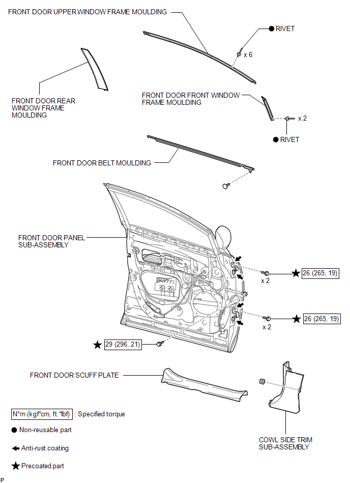
ILLUSTRATION
.png)
ILLUSTRATION
.png)
ILLUSTRATION

 Installation
INSTALLATION
PROCEDURE
1. INSTALL FRONT DOOR FRONT WINDOW FRAME MOULDING
(a) Engage the front door front window frame moulding to the door frame.
...
Other materials about Toyota Venza:
Door Control Transmitter(w/o Smart Key System)
Components
COMPONENTS
ILLUSTRATION
Removal
REMOVAL
PROCEDURE
1. REMOVE TRANSMITTER HOUSING COVER
2. REMOVE DOOR CONTROL TRANSMITTER MODULE
Inspection
INSPECTION
PROCEDURE
1. INSPECT DOOR CONTROL TRANSMITTER
(a) Inspect operation of th ...
Power Steering ECU Communication Stop Mode
DESCRIPTION
Detection Item
Symptom
Trouble Area
Power Steering ECU Communication Stop Mode
"EPS" is not displayed on "CAN Bus Check" screen of the Techstream.
...
Air Conditioning Amplifier Communication Stop Mode
DESCRIPTION
Detection Item
Symptom
Trouble Area
Air Conditioning Amplifier Communication Stop Mode
"Air Conditioner" is not displayed on "CAN Bus Check" screen
o ...

0.129