Toyota Venza: Components
COMPONENTS
ILLUSTRATION
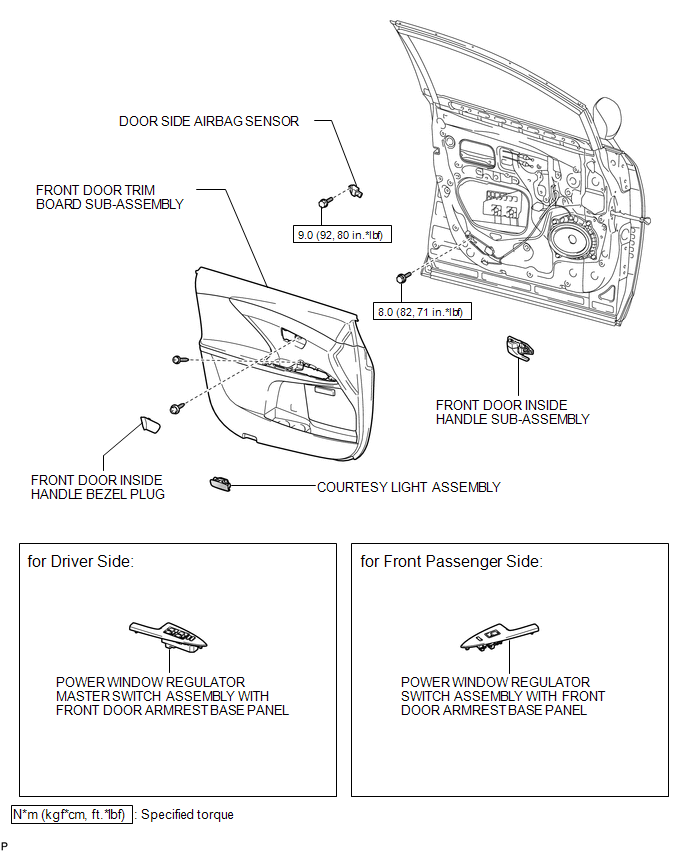
ILLUSTRATION

ILLUSTRATION
.png)

 Installation
INSTALLATION
PROCEDURE
1. REPAIR INSTRUCTION
(a) Clean the vehicle body surface.
(1) Using a heat light, heat the vehicle body surface.
Heating Temperature
Item
Temperature ...
Other materials about Toyota Venza:
Removal
REMOVAL
PROCEDURE
1. REMOVE INSTRUMENT PANEL REINFORCEMENT ASSEMBLY WITH AIR CONDITIONING UNIT
(See page )
2. REMOVE COOL AIR INTAKE DUCT SEAL
3. REMOVE INLET NO. 2 AIR CLEANER
4. REMOVE AIR CLEANER CAP WITH HOSE
5. REMOVE AIR CLEANER CASE
...
Problem Symptoms Table
PROBLEM SYMPTOMS TABLE
HINT:
Use the table below to help determine the cause of problem symptoms.
If multiple suspected areas are listed, the potential causes of the symptoms
are listed in order of probability in the "Suspected Area" ...
System Description
SYSTEM DESCRIPTION
1. GENERAL
(a) Deceleration sensors used for the airbag system are installed on various
parts on the vehicle and calculate the deceleration rate of each part during a collision.
(b) Depending on the situation, the center airbag sensor a ...

0.1249