Toyota Venza: Components
COMPONENTS
ILLUSTRATION
ILLUSTRATION
.png)
ILLUSTRATION
.png)
ILLUSTRATION
ILLUSTRATION

 Removal
REMOVAL
PROCEDURE
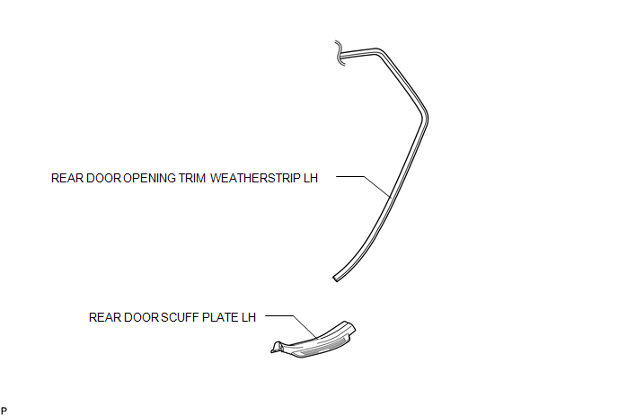
1. REMOVE REAR DOOR SCUFF PLATE LH
2. DISCONNECT REAR DOOR OPENING TRIM WEATHERSTRIP LH
3. REMOVE TONNEAU COVER ASSEMBLY (w/ Tonneau Cover)
4. REMOVE DECK BOARD ASSEMBL ...
Other materials about Toyota Venza:
Lost Communication with AFS LIN (B124D)
DESCRIPTION
The DTC is stored when the main body ECU (driver side junction block assembly)
detects malfunctions in the LIN communication system.
DTC No.
DTC Detection Condition
Trouble Area
B124D
...
Front Speed Sensor RH Circuit (C0200/31,C0205/32,C1271/71,C1272/72,C1330/35,C1331/36)
DESCRIPTION
The speed sensor detects wheel speed and sends the appropriate signals to the
skid control ECU. These signals are used for the ABS control system.
Speed sensor rotors have 48 serrations. The hall IC type speed sensor use the
frequency of outp ...
Body
General Maintenance
GENERAL MAINTENANCE
PROCEDURE
1. TIGHTEN BOLTS AND NUTS ON CHASSIS AND BODY
(a) If necessary, tighten the bolts and nuts on the chassis parts listed below.
Front axle and suspension
Drivetrain
Rear axle and suspension ...

0.1615