Toyota Venza: Components
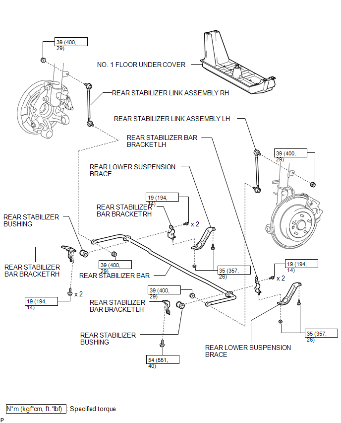
COMPONENTS
ILLUSTRATION

 Inspection
INSPECTION
PROCEDURE
1. INSPECT REAR STABILIZER LINK ASSEMBLY
(a) Move the ball joint stud back and forth 5 times before installing
the nut as shown in the illustration.
...
Other materials about Toyota Venza:
Door Control Transmitter(w/o Smart Key System)
Components
COMPONENTS
ILLUSTRATION
Removal
REMOVAL
PROCEDURE
1. REMOVE TRANSMITTER HOUSING COVER
2. REMOVE DOOR CONTROL TRANSMITTER MODULE
Inspection
INSPECTION
PROCEDURE
1. INSPECT DOOR CONTROL TRANSMITTER
(a) Inspect operation of th ...
Data List / Active Test
DATA LIST / ACTIVE TEST
1. DATA LIST
HINT:
Using the Techstream to read the Data List allows the values or states of switches,
sensors, actuators and other items to be read without removing any parts. This non-intrusive
inspection can be very useful bec ...
Disassembly
DISASSEMBLY
PROCEDURE
1. REMOVE NO. 1 SIDE DEFROSTER NOZZLE DUCT
(a) Remove the 2 screws <E> or <F> and remove the No. 1 side defroster
nozzle duct.
2. REMOVE NO. 2 SIDE DEFROSTER NO ...

0.125