Toyota Venza: Components
COMPONENTS
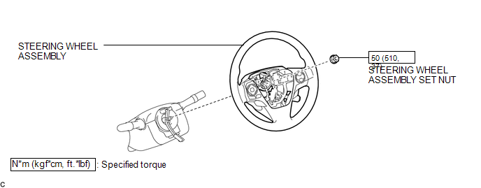
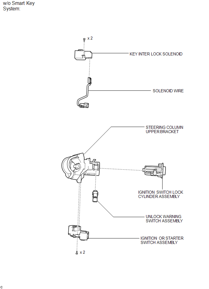
ILLUSTRATION
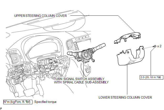
ILLUSTRATION
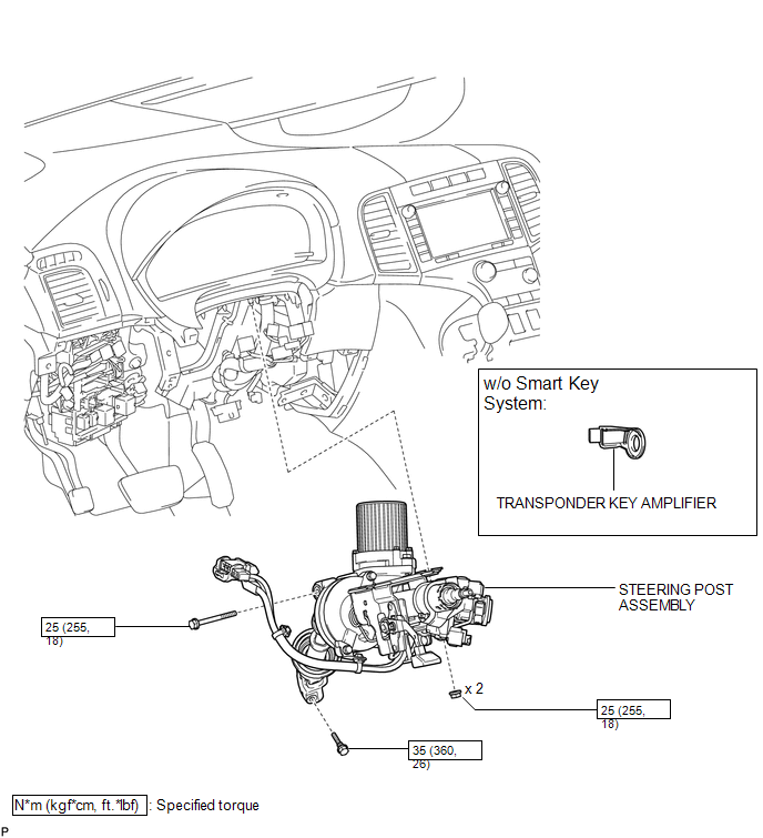
ILLUSTRATION
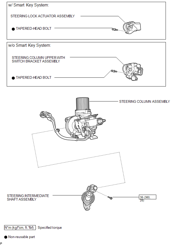
ILLUSTRATION
ILLUSTRATION

 Removal
REMOVAL
CAUTION / NOTICE / HINT
CAUTION:
Some of these service operations affect the SRS airbag system. Read the precautionary
notices concerning the SRS airbag system before servicing the steeri ...
Other materials about Toyota Venza:
Purge Valve
Components
COMPONENTS
ILLUSTRATION
Inspection
INSPECTION
PROCEDURE
1. INSPECT NO. 1 VACUUM SWITCHING VALVE ASSEMBLY
(a) Measure the resistance according to the value(s) in the table below.
Standard Resistance:
Te ...
Removal
REMOVAL
CAUTION / NOTICE / HINT
HINT:
Use the same procedure for the LH side and RH side.
The following procedure is for the LH side.
If the sensor rotor needs to be replaced, replace it together with the
rear drive shaft assembly.
...
Diagnosis System
DIAGNOSIS SYSTEM
1. DESCRIPTION
(a) When troubleshooting On-Board Diagnostic (OBD II) vehicles, the vehicle must
be connected to the OBD II scan tool (complying with SAE J1987). Various data output
from the vehicle TCM can then be read.
(b) OBD II regul ...

0.1677