Toyota Venza: Adjustment
ADJUSTMENT
CAUTION / NOTICE / HINT
CAUTION:
Before adjusting the door positions of vehicles equipped with side and curtain shield airbags, be sure to disconnect the battery. After adjustment, check that the SRS warning light is operating normally and there are no SRS DTCs output.
HINT:
- Use the same procedure for the RH side and LH side.
- The procedure listed below is for the LH side.
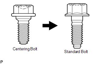
- Centering bolts are used to mount the door hinge to the vehicle body and door. The door cannot be adjusted with the centering bolts installed on it. Substitute the centering bolts with standard bolts when making adjustments.
- Specified torque for standard bolts is shown in the standard bolt chart
(See page
.gif) ).
).
PROCEDURE
1. INSPECT FRONT DOOR
(a) Check that the clearance measurements of areas *1 through *23 are within each standard range.
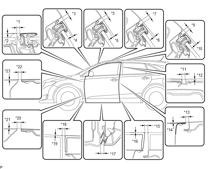 Standard Clearance
|
Area |
Measurement |
Area |
Measurement |
|---|---|---|---|
|
*1 |
3.0 to 7.0 mm (0.118 to 0.276 in.) |
*13 |
3.0 to 6.0 mm (0.118 to 0.236 in.) |
|
*2 |
-1.0 to 3.0 mm (-0.0394 to 0.118 in.) |
*14 |
-1.5 to 1.5 mm (-0.0591 to 0.0591 in.) |
|
*3 |
3.5 to 6.5 mm (0.138 to 0.256 in.) |
*15 |
3.2 to 7.2 mm (0.126 to 0.283 in.) |
|
*4 |
0.3 to 3.3 mm (0.0118 to 0.130 in.) |
*16 |
-2.0 to 2.0 mm (-0.0787 to 0.0787 in.) |
|
*5 |
3.5 to 6.5 mm (0.138 to 0.256 in.) |
*17 |
9.3 to 13.3 mm (0.366 to 0.524 in.) |
|
*6 |
1.3 to 4.3 mm (0.0511 to 0.169 in.) |
*18 |
3.2 to 7.2 mm (0.126 to 0.283 in.) |
|
*7 |
3.5 to 6.5 mm (0.138 to 0.256 in.) |
*19 |
-2.0 to 2.0 mm (-0.0787 to 0.0787 in.) |
|
*8 |
1.2 to 4.2 mm (0.0472 to 0.165 in.) |
*20 |
3.0 to 6.0 mm (0.118 to 0.236 in.) |
|
*9 |
3.5 to 6.5 mm (0.138 to 0.256 in.) |
*21 |
-1.5 to 1.5 mm (-0.0591 to 0.0591 in.) |
|
*10 |
0.6 to 3.6 mm (0.0236 to 0.141 in.) |
*22 |
3.0 to 6.0 mm (0.118 to 0.236 in.) |
|
*11 |
2.5 to 6.5 mm (0.0984 to 0.256 in.) |
*23 |
-1.5 to 1.5 mm (-0.0591 to 0.0591 in.) |
|
*12 |
-2.0 to 2.0 mm (-0.0787 to 0.0787 in.) |
- |
- |
2. DISCONNECT CABLE FROM NEGATIVE BATTERY TERMINAL
CAUTION:
Wait at least 90 seconds after disconnecting the cable from the negative (-)
battery terminal to disable the SRS system (See page
).
NOTICE:
When disconnecting the cable, some systems need to be initialized after the cable
is reconnected (See page ).
3. ADJUST FRONT DOOR
|
(a) Using SST, loosen the hinge bolts on the vehicle body and adjust the door position. SST: 09812-00010 |
|
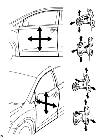
(b) Tighten the hinge bolts on the vehicle body after the adjustment.
Torque:
26 N·m {265 kgf·cm, 19 ft·lbf}
(c) Loosen the hinge bolts on the door and adjust the door position.
(d) Tighten the hinge bolts on the door after the adjustment.
Torque:
26 N·m {265 kgf·cm, 19 ft·lbf}
|
(e) Using a T40 "TORX" socket wrench, slightly loosen the striker mounting screws. |
|
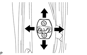
(f) Using a brass bar and a hammer, hit the striker to adjust its position.
(g) Using a T40 "TORX" socket wrench, tighten the striker mounting screws after the adjustment.
Torque:
23 N·m {235 kgf·cm, 17 ft·lbf}
4. CONNECT CABLE TO NEGATIVE BATTERY TERMINAL
NOTICE:
When disconnecting the cable, some systems need to be initialized after the cable
is reconnected (See page ).
5. INSPECT SRS WARNING LIGHT
(See page )
 Disassembly
DISASSEMBLY
PROCEDURE
1. PRECAUTION
NOTICE:
After turning the ignition switch off, waiting time may be required before disconnecting
the cable from the negative (-) battery terminal. Therefore, ...
 Reassembly
REASSEMBLY
PROCEDURE
1. PRECAUTION
NOTICE:
After turning the ignition switch off, waiting time may be required before disconnecting
the cable from the negative (-) battery terminal. Therefore, m ...
Other materials about Toyota Venza:
Removal
REMOVAL
PROCEDURE
1. REMOVE NO. 1 ENGINE COVER SUB-ASSEMBLY
2. REMOVE CAMSHAFT TIMING OIL CONTROL VALVE ASSEMBLY (for Exhaust Side)
(a) Disconnect the oil control valve connector.
(b) Remove the ...
Dtc Check / Clear
DTC CHECK / CLEAR
1. CHECK DTC
(a) Connect the Techstream to the DLC3.
(b) Turn the engine switch on (IG).
(c) Turn the clearance sonar main switch on.
(d) Turn the Techstream on.
(e) Enter the following menus: Body Electrical / Intuitive P/A / DTC.
(f) ...
If you think something is wrong
If you notice any of the following symptoms, your vehicle probably needs adjustment
or repair. Contact your Toyota dealer as soon as possible.
- Visible symptoms
• Fluid leaks under the vehicle
(Water dripping from the air conditioning after use i ...

0.166