Toyota Venza: Components
COMPONENTS
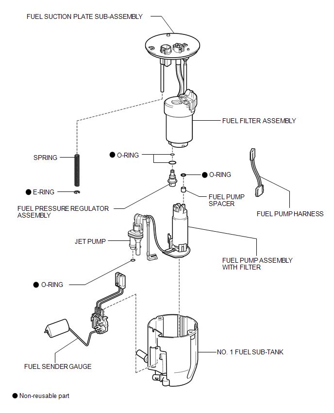
ILLUSTRATION

 Removal
REMOVAL
PROCEDURE
1. REMOVE FUEL SUCTION TUBE ASSEMBLY WITH PUMP AND GAUGE
(a) Remove the fuel suction tube assembly with pump and gauge (See page
).
2. REMOVE FUEL SENDER GAUGE
3. REMOVE FU ...
Other materials about Toyota Venza:
Startability Malfunction (P1604)
DESCRIPTION
This DTC is stored when the engine does not start even though the STA signal
is input or when the engine takes a long time to start, and when the engine speed
is low or the engine stalls just after the engine starts.
Using the Techstream, the ...
Vehicle Specifications have not been Stored (B2451)
DESCRIPTION
The headlight leveling ECU assembly stores this DTC if the vehicle specifications
have not been stored in the ECU.
HINT:
The vehicle specifications are stored in the ECU at the factory.
DTC No.
DTC Detecting Condition
...
Initialization
INITIALIZATION
NOTICE:
Make sure that the front passenger seat is not occupied before performing the
operation.
HINT:
Perform zero point calibration and sensitivity check if any of the following
conditions occur:
The occupant classification ECU ...

0.1599