Toyota Venza: Components
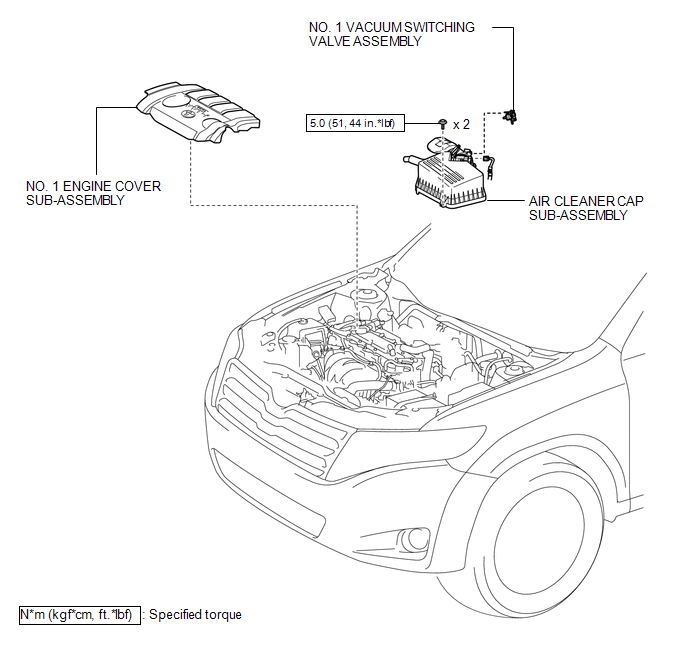
COMPONENTS
ILLUSTRATION
.png)
ILLUSTRATION
ILLUSTRATION
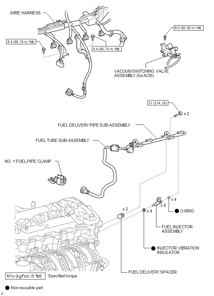
 Fuel Injector
...
 Removal
REMOVAL
CAUTION / NOTICE / HINT
HINT:
Perform "Inspection After Repair" after replacing the fuel injector assembly
(See page ).
PROCEDURE
1. DISCHARGE FUEL SYSTEM PRESSURE
(a) Disch ...
Other materials about Toyota Venza:
Selecting the units
Press the “US/M-M” button.
The unit changes each time the button is pressed.
- Liquid crystal display
Small spots or light spots may appear on the display. This phenomenon is characteristic
of liquid crystal displays, and there is no problem to ...
Starting System
Parts Location
PARTS LOCATION
ILLUSTRATION
ILLUSTRATION
System Diagram
SYSTEM DIAGRAM
...
Air Inlet Damper Control Servo Motor Circuit (B1442/42)
DESCRIPTION
The air inlet control servo motor sends pulse signals to indicate the damper
position to the A/C amplifier. The A/C amplifier activates the motor (normal or
reverse) based on these signals to move the air inlet mode selection air inlet control ...

0.1501