Toyota Venza: Combination Meter
Components
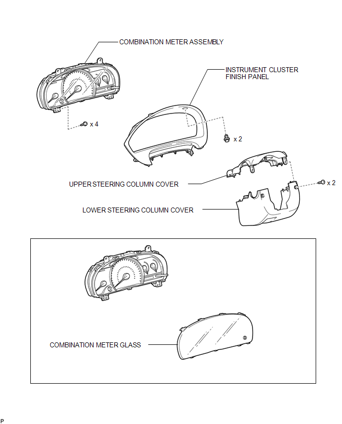
COMPONENTS
ILLUSTRATION
Disassembly
DISASSEMBLY
PROCEDURE
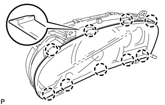
1. REMOVE COMBINATION METER GLASS
|
(a) Disengage the 9 claws to remove the combination meter glass. |
|
Removal
REMOVAL
PROCEDURE
1. REMOVE LOWER STEERING COLUMN COVER
.gif)
2. REMOVE UPPER STEERING COLUMN COVER
3. DISCONNECT CABLE FROM NEGATIVE BATTERY TERMINAL
NOTICE:
When disconnecting the cable, some systems need to be initialized after the cable
is reconnected (See page ).
4. REMOVE INSTRUMENT CLUSTER FINISH PANEL
|
(a) Remove the 2 clips. |
|
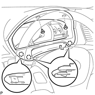
(b) Disengage the 3 claws and remove the instrument cluster finish panel.
5. REMOVE COMBINATION METER ASSEMBLY
|
(a) Remove the 4 screws. |
|
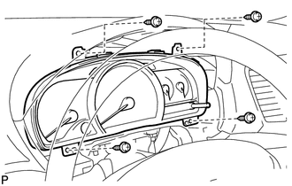
(b) Disconnect the connectors and remove the combination meter assembly.
Reassembly
REASSEMBLY
PROCEDURE
1. INSTALL COMBINATION METER GLASS
|
(a) Engage the 9 claws to install the combination meter glass. |
|
.png)
Installation
INSTALLATION
PROCEDURE
1. INSTALL COMBINATION METER ASSEMBLY
|
(a) Connect the connectors. |
|
.png)
(b) Install the combination meter assembly with the 4 screws.
2. INSTALL INSTRUMENT CLUSTER FINISH PANEL
|
(a) Engage the 3 claws. |
|
.png)
(b) Install the instrument cluster finish panel with the 2 clips.
3. CONNECT CABLE TO NEGATIVE BATTERY TERMINAL
NOTICE:
When disconnecting the cable, some systems need to be initialized after the cable
is reconnected (See page .gif) ).
).
4. INSTALL UPPER STEERING COLUMN COVER
5. INSTALL LOWER STEERING COLUMN COVER
 Problem Symptoms Table
PROBLEM SYMPTOMS TABLE
HINT:
Use the table below to help determine the cause of problem symptoms. If multiple
suspected areas are listed, the potential causes of the symptoms are listed in order
...

Other materials about Toyota Venza:
On-vehicle Inspection
ON-VEHICLE INSPECTION
PROCEDURE
1. CHECK FOR FUEL PUMP OPERATION AND INSPECT FOR FUEL LEAK
(a) Check fuel pump operation.
(1) Connect the Techstream to the DLC3.
(2) Turn the ignition switch to ON and turn the Techstream on.
NOTICE:
Do not start the eng ...
Data Signal Circuit between Radio Receiver and Stereo Jack Adapter
DESCRIPTION
The No. 1 stereo jack adapter assembly sends the sound data signal or image data
signal from a USB device to the radio and display receiver assembly via this circuit.
WIRING DIAGRAM
PROCEDURE
1.
CHECK HARNESS AND CONN ...
Fail-safe Chart
FAIL-SAFE CHART
1. POWER WINDOW OPERATION IN FAIL-SAFE MODE
HINT:
If the pulse sensor built into the power window regulator motor malfunctions,
the power window control system enters fail-safe mode.
(a) The power window control system prohibits the follo ...

0.1159