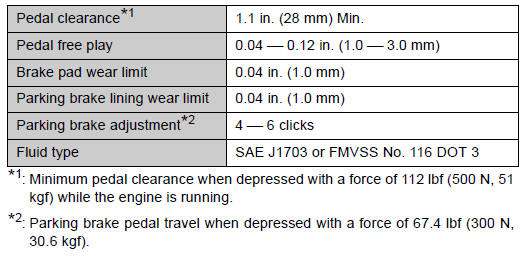
Toyota Venza: Brakes
 Automatic transaxle
NOTICE
- Automatic transaxle fluid type
Using transaxle fluid other than “Toyota Genuine ATF WS” may cause deterioration
in shift quality, locking up of your transaxle accompanied by v ...
 Steering
...
Other materials about Toyota Venza:
Removal
REMOVAL
PROCEDURE
1. REMOVE WHEEL ASSEMBLY
2. REMOVE TIRE PRESSURE WARNING VALVE AND TRANSMITTER
(a) Remove the tire valve cap.
NOTICE:
Keep the removed tire valve cap.
(b) Remove the valve core to release the air from the tire.
NOTICE:
Make sure that ...
Back Door Closer Switch Malfunction (B2251)
DESCRIPTION
The power back door ECU (power back door motor unit)*1 or back door closer ECU
(multiplex network door ECU)*2 receives signals from the latch switch, sector switch
and back door courtesy switch, which are built into the back door lock. Based o ...
Inspection
INSPECTION
PROCEDURE
1. INSPECT THROTTLE BODY ASSEMBLY
Text in Illustration
*1
Component without harness connected
(Throttle Body)
(a) Check that the throttle valve opens and closes smoothly.
(b) Check that there is no ...

0.1164