Toyota Venza: Parking Brake System
Problem Symptoms Table
PROBLEM SYMPTOMS TABLE
HINT:
Use the table below to help determine the cause of problem symptoms. If multiple suspected areas are listed, the potential causes of the symptoms are listed in order of probability in the "Suspected Area" column of the table. Check each symptom by checking the suspected areas in the order they are listed. Replace parts as necessary.
Parking Brake System|
Symptom |
Suspected Area |
See page |
|---|---|---|
|
Parking brake drag |
Parking brake pedal travel (Out of adjustment) |
|
|
Parking brake cable (Sticking) |
|
|
|
Parking brake shoe clearance (Out of adjustment) |
|
|
|
Parking brake shoe lining (Cracked or distorted) |
|
|
|
Tension or return spring (Damaged) |
|
.gif)
Adjustment
ADJUSTMENT
PROCEDURE
1. INSPECT PARKING BRAKE PEDAL TRAVEL
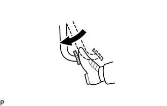
(a) Fully depress the parking brake pedal to engage the parking brake.
(b) Depress the pedal again to disengage the parking brake.
|
(c) Slowly depress the parking brake pedal using the specified force, and count the number of clicks. Parking brake pedal travel: 4 to 6 notches at 300 N (31 kgf, 67.5 lbf) If the parking brake pedal travel is not as specified, adjust the parking brake shoe clearance and parking brake pedal travel. |
|
2. ADJUST PARKING BRAKE SHOE CLEARANCE AND PARKING BRAKE PEDAL TRAVEL
(a) Completely release the parking brake pedal.
|
(b) Loosen the lock nut and No. 1 wire adjusting nut to completely release the parking brake cable. Text in Illustration
|
|
.png)
(c) Remove the rear wheel.
(d) Temporarily install the 5 hub nuts.
(e) Remove the shoe adjusting hole plug.
|
(f) Turn the shoe adjuster and expand the shoe until the disc locks. |
|
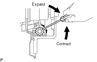
(g) Turn and contract the shoe adjuster until the disc can rotate smoothly.
Standard:
Returns 8 notches.
(h) Check that there is no brake drag against the shoe.
(i) Install the shoe adjusting hole plug.
(j) Turn the adjusting nut until the parking brake pedal travel is corrected to be within the specified range.
Parking brake pedal travel:
4 to 6 notches at 300 N (31 kgf, 67.5 lbf)
(k) Using a wrench or an equivalent tool, hold the adjusting nut and tighten the lock nut.
Torque:
5.4 N·m {55 kgf·cm, 48 in·lbf}
(l) Operate the parking brake pedal 3 to 4 times, and check the parking brake pedal travel.
(m) Check that there is no brake drag against the shoe.
(n) Remove the 5 hub nuts.
(o) Install the rear wheel.
Torque:
103 N·m {1050 kgf·cm, 76 ft·lbf}
3. INSPECT BRAKE WARNING LIGHT
(a) When operating the parking brake pedal, check that the brake warning light illuminates.
Standard:
The brake warning light always illuminates at the first notch.
 Installation
INSTALLATION
PROCEDURE
1. INSTALL PARKING BRAKE SWITCH ASSEMBLY
(a) Install the parking brake switch assembly with the screw.
Torque:
0.9 N·m {9 kgf·cm, 8 in·lbf}
...

Other materials about Toyota Venza:
On-vehicle Inspection
ON-VEHICLE INSPECTION
CAUTION / NOTICE / HINT
HINT:
Use the same procedure for the RH side and LH side.
The procedure listed below is for the LH side.
PROCEDURE
1. REMOVE REAR WHEEL
2. SEPARATE REAR FLEXIBLE HOSE
3. SEPARATE REAR DI ...
Cruise control
Use the cruise control to maintain a set speed without depressing the accelerator
pedal.
1. Indicators
2. Cruise control switch
- Set the vehicle speed
Press the “ON-OFF” button to activate the cruise control.
Cruise control indicator will ...
Customize Parameters
CUSTOMIZE PARAMETERS
1. CUSTOMIZE METER / GAUGE SYSTEM
(a) Customizing with the Techstream
(1) Connect the Techstream to the DLC3.
(2) Turn the ignition switch to ON.
(3) Turn the Techstream on.
(4) Enter the following menus: Customize Setting / Warning. ...

0.1149